Tiny Terminal
17th February 2015
This article describes a simple character terminal, which provides 8 lines of 21 characters per line. It's driven by a standard 9600 baud serial interface, and is ideal for debugging serial devices, or as a self-contained character display for a project:
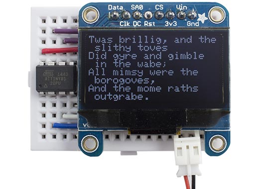
The Tiny Terminal serial terminal provides eight lines of 21 characters per line.
The display and serial input are both handled by a diminuitive 8-pin ATtiny85. Here's an application of the Tiny Terminal, displaying the NMEA sentences from a GPS module:
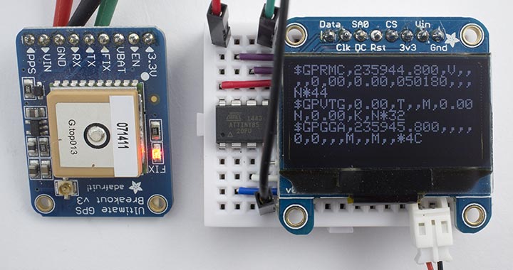
Using the Tiny Terminal to display the serial output from a GPS module.
Design
The Tiny Terminal is based on a 128x64 OLED display, a small display about 3.5cm (1.4") wide with a very clear, bright monochrome display, and an SPI/I2C interface, available from Adafruit [1], or Pimoroni [2].
The Tiny Terminal circuit uses an ATtiny85, and it takes advantage of the fact that the display stores the data written to the display in its own internal memory, so for this application there's no need for a separate memory buffer. The display is divided into eight 8-pixel high bands, referred to as pages, and you can write a vertical column of 8 pixels at a time. It's therefore easy to write 8 x 6 bitmap characters to the display; you just specify the page and starting column, and then write the character definitions for successive characters [3].
Plotting characters
The terminal program writes characters to successive character positions on the display. When you reach the end of the bottom line of the display it scrolls the display up, just like on a terminal, so you always see the last 8 lines written to the display. The scrolling is handled automatically by the display's Display Offset command.
Here's a simplified example showing how characters are plotted to the display. First we define the bitmap definitions of the character set. Here are the definitions for the characters 0 to 9:
char CharMap[10][6] = {
{ 0x3E, 0x51, 0x49, 0x45, 0x3E, 0x00 },
{ 0x00, 0x42, 0x7F, 0x40, 0x00, 0x00 },
{ 0x72, 0x49, 0x49, 0x49, 0x46, 0x00 },
{ 0x21, 0x41, 0x49, 0x4D, 0x33, 0x00 },
{ 0x18, 0x14, 0x12, 0x7F, 0x10, 0x00 },
{ 0x27, 0x45, 0x45, 0x45, 0x39, 0x00 },
{ 0x3C, 0x4A, 0x49, 0x49, 0x31, 0x00 },
{ 0x41, 0x21, 0x11, 0x09, 0x07, 0x00 },
{ 0x36, 0x49, 0x49, 0x49, 0x36, 0x00 },
{ 0x46, 0x49, 0x49, 0x29, 0x1E, 0x00 }
};
Then here's the routine to plot a character:
void PlotChar(char c, int line, int column) {
  column = column*6;
  Command(0xB0 + (line & 0x07));   // Page
  Command(0x00 + (column & 0x0F)); // Column start low
  Command(0x10 + (column >> 4));   // Column start high
  for (int col = 0 ; col < 6; col++) {
    Data(CharMap[c][col]);
  }
}
where a call to Command() writes a control command to the display, and a call to Data() writes a data byte to the display. For example, to plot a "3" in column 0 of the bottom line of the display the call would be:
PlotChar(3, 7, 0);
The full Tiny Terminal program provides bitmaps for the 96 characters from ASCII 32 (space) up to 127, and they are stored in program memory to save RAM space on the ATtiny85.
Control characters
Characters are printed to the terminal using the routine Print(). This calls PlotChar() to print the characters 32 to 127, and handles control characters. Currently the only control character supported is Return, which returns the printing position to the start of the next line, calling ScrollDisplay() to scroll the display if necessary.
If you wanted to use the Tiny Terminal to display a control panel you might want to add cursor addressing, to allow you to move the printing position to any character position on the display.
Optimising the display routine
At the 9600 baud rate we're using, characters are being received on the serial input at approximately 1msec intervals, so we need to make sure that we always take less than 1msec to write a character to the display.
The slowest operation is clearing the line before scrolling the display. I tested how long this takes by setting the serial pin to be an output, and then making the main loop:
void loop () {
  // Time scroll delay
  ScrollDisplay();
  PINB = 1<<serial;
}
This toggles the serial pin each time the screen is scrolled. By measuring the frequency on the serial pin we can calculate how long the routine takes to execute. I used the frequency measurement mode on my ET-1700 pocket multimeter (available on eBay).
Here's the original version of the routine to clear a line on the display:
void ClearLine (int line) {
  Command(0xB0 + line);
  Command(0x00); // Column start low
  Command(0x00); // Column start high
  for (uint8_t b = 0 ; b < 128; b++) Data(0);
}
This gave a frequency of 20Hz, meaning that the routine was taking 25msec; a factor of 25 too slow!
After several successive optimisations I finally arrived at this version of the routine:
void Clear256() {
  uint8_t b = 0;
  do {
    PINB = 1<<clk; // clk low
    b++;
    PINB = 1<<clk; // clk high
  } while (b != 0);
}

// Optimised for fast scrolling
void ClearLine (int line) {
  Command(0xB0 + line);
  Command(0x00); // Column start low
  Command(0x00); // Column start high
  PINB = 1<<cs; // cs low
  PORTB = PORTB & ~(1<<data); // data low
  Clear256(); Clear256(); Clear256(); Clear256();
  PINB = 1<<cs; // cs high
}
This increases the frequency to 660Hz, equivalent to an execution time of 0.75msec, or a factor of 33 improvement!
The main optimisation is to replace the Arduino calls to digitalWrite() with:
PORTB = PORTB & ~(1<<bit);
to clear a bit,
PORTB = PORTB | 1<<bit;
to set a bit, and:
PINB = 1<<bit;
to toggle a bit. It uses the following additional optimisations:
- The data bit is always zero, so we only need to set it once outside the loop.
- We can keep cs low for the entire routine, rather than taking it low for each byte.
- We clear the display in four chunks of 256 bits, to allow the use of a single byte loop counter.
Serial interface
The serial interface is based on my earlier article Simple ATtiny USI UART. However, in this case there aren't enough pins left on the ATtiny85 to use a crystal clock, so the Tiny Terminal uses the ATtiny85's default internal 8MHz clock. The factory calibration is quoted as accurate to within 10%, which may not be accurate enough for correct operation of the serial UART. You may be lucky, and find that it's close enough, but I found I needed to calibrate the internal clock using the OSCCAL register provided in the ATtiny85, with a statement in setup() such as:
OSCCAL = 0x81;
There are two ways of calibrating the clock:
- Provide a serial input stream, such as the output from a GPS module, and modify the OSCCAL value until the Tiny Terminal displays the correct characters.
- Generate a frequency on the serial pin, measure the frequency with a frequency meter, and adjust the OSCCAL value until you get the correct value.
I used the second approach, using Timer/Counter0 to generate a 1/64 of the clock frequency on I/O pin 0:
pinMode(serial, OUTPUT);
TCCR0A = 1<<COM0A0 | 2<<WGM00 ; // Toggle OC0A
TCCR0B = 3<<CS00; // Clock/64 giving 62.5kHz
I then recompiled the program with different OSCCAL values until the meter read 62.5kHz.
If you don't want to be bothered with calibrating the internal oscillator use an ATtiny84, which provides enough pins to allow you to have an external 8MHz crystal.
The serial UART receives each character and stores it in the global variable RecdByte. The main loop then simply waits for a character to be received, and prints it to the display:
void loop () {
  while (RecdByte == 0);
  char temp = RecdByte;
  RecdByte = 0;
  Print(temp);
}
Circuit
The circuit is straightforward:
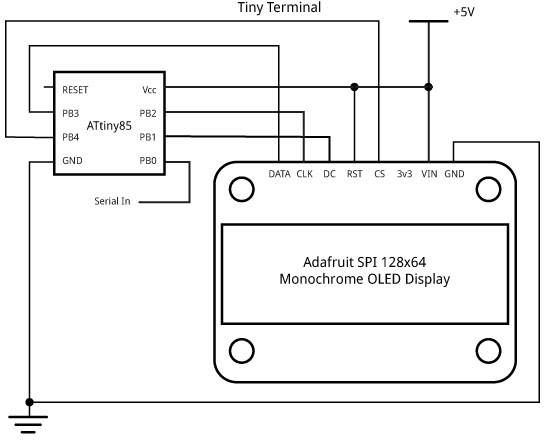
Tiny Terminal circuit.
Compiling the program
I compiled the program using the Arduino-Tiny core extension to the Arduino IDE [4], setting the fuses with the ATtiny85 @ 8MHz (internal oscillator; BOD disabled) option on the Board submenu, and uploaded the program to the ATtiny85 using the Tiny AVR Programmer Board; see ATtiny-Based Beginner's Kit. It's just over 2Kbytes, so would fit on an ATtiny45.
Here's the whole Tiny Terminal program: Tiny Terminal Program.
Updates
19th February 2015: I've updated the definition of loop() to solve a problem that occasionally missed a character from the serial input.
6th May 2015: I've updated the program to use the improved Simple ATtiny USI UART 2.
6th August 2016: I've updated the definition of CharMap to work with Arduino IDE version 1.6.8. I have also tested compiling the program using Spence Konde's excellent new ATTiny Core, which supports all the ATtiny processors and supersedes the various earlier ATtiny cores [5]. Select the ATtinyx5 series option under the ATtiny Universal heading on the Boards menu. Then choose CPU, B.O.D. Disabled, ATtiny85, 8 MHz (internal) from the subsequent menus. Choose Burn Bootloader to set the fuses appropriately. Then upload the program to the ATtiny85.
- ^ Monochrome 1.3" 128x64 OLED Graphic Display on Adafruit.
- ^ Monochrome 1.3" 128x64 OLED Graphic Display on Pimoroni.
- ^ SSD1306 Datasheet on Adafruit.
- ^ Arduino-Tiny core on Google Code.
- ^ ATTinyCore on GitHub.
blog comments powered by Disqus