New ATtiny Low Power
15th October 2019
This article describes how to use the new 0-series and 1-series ATtiny microcontrollers in low-power projects, taking advantage of sleep mode to maximise the battery life and avoid the need for an on/off switch. The project is a simple 15-minute timer that flashes an LED once every 2 seconds while it is counting down, and then beeps a piezo buzzer when the time has expired.
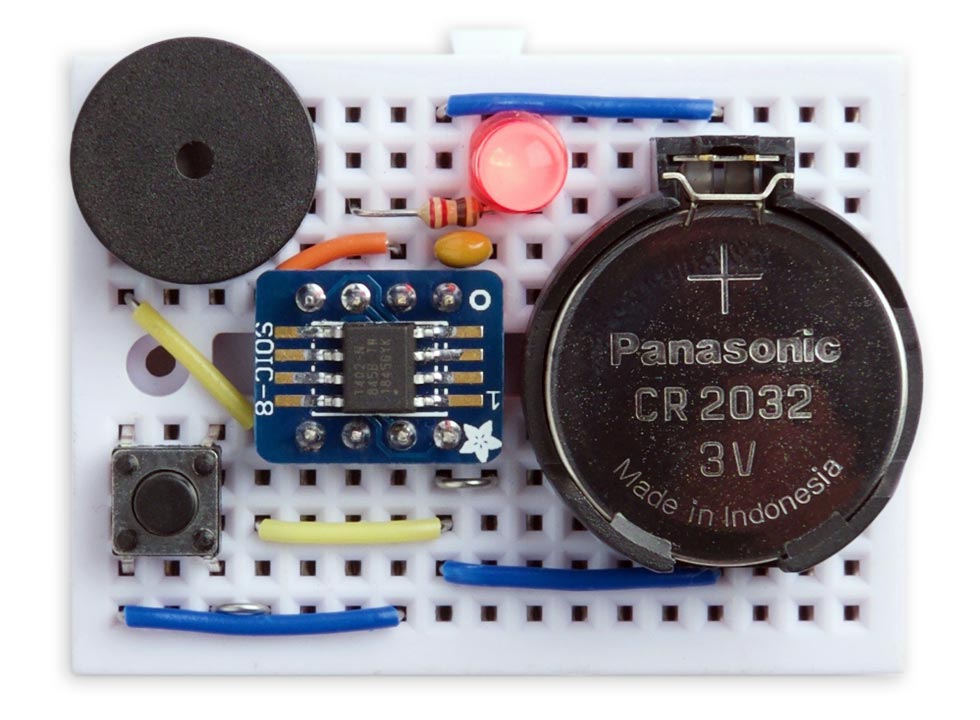
Timer running on an ATtiny402 to demonstrate the low power sleep mode.
You could use it as the basis for an egg timer, a bath-overflow alarm, or any other fixed timer application.
Introduction
I thought it would be interesting to compare the low-power performance of the new 0-series ATtiny microcontrollers with my old favourite, the ATtiny85. One of my first projects based on the ATtiny85 was a simple 15-minute timer that took advantage of the low-power sleep mode to avoid the need for an on/off switch, and this has turned out to be one of my most popular articles: ATtiny Low Power.
I thought it would be interesting to try and reproduce the project with one of the new 0-series ATtiny chips from Microchip, to compare the power consumption in the low-power sleep mode between the two devices. For more information about these chips see Getting Started with the New ATtiny Chips.
For the comparison I chose the chip that's closest in specification to the ATtiny85: the 0-series ATtiny402, an 8-pin microcontroller with 4Kbytes of flash memory. The project doesn't use much memory so the 2Kbyte ATtiny202 would do equally well.
The circuit
Here's the circuit of the timer based on the ATtiny402:
Circuit of the low-power ATtiny402 timer.
The ATtiny402 is only available in an SOIC package so I mounted it on a compact breakout board from Adafruit [1] or Pimoroni in the UK [2], but similar boards are available from AliExpress [3]. A suitable piezo buzzer is available from Adafruit [4].
It all fits neatly on a SparkFun mini breadboard [5], available in the UK from Hobbytronics [6].
The program
Sleep mode
Like the earlier ATtiny85, the ATtiny402 provides three different sleep modes: idle, standby, and power-down. The power-down sleep mode gives the lowest power consumption; this turns off the processor and all the peripherals apart from the watchdog timer (WDT) and Periodic Interval Timer (PIT) part of the RTC. There are three ways to wake the processor from sleep:
- With a pin-sense interrupt.
- With a TWI address match.
- With a timeout on the Periodic Interval Timer.
My original low-power timer for the ATtiny85 used a reset to wake the processor from sleep, but there is no reset pin on the newer ATtiny processors by default, so in this application I need to use a pin-sense interrupt.
To choose the sleep mode we want to use, call:
set_sleep_mode(SLEEP_MODE_PWR_DOWN);
sleep_enable();
We then execute sleep mode by executing:
sleep_cpu();
Pin-sense interrupt
The new AVR processors support four types of interrupt on every pin: Sense both edges (BOTHEDGES), sense rising edges (RISING), sense falling edges (FALLING), and sense low level (LEVEL).
PORTA.PIN3CTRL = PORT_PULLUPEN_bm | PORT_ISC_LEVEL_gc;
If you wanted a different sense type, replace the word LEVEL by BOTHEDGES, RISING, or FALLING as appropriate.
We also need to provide an interrupt service routine, but because we're just using the interrupt to wake the processor from sleep this doesn't need to do anything other than clear the PA3 interrupt flag:
ISR(PORTA_PORT_vect) {
  PORTA.INTFLAGS = PORT_INT3_bm;
}
Accuracy
The timer duration is specified, in milliseconds, by the statement:
const unsigned long Alarm = 900000;
During testing I reduced the time to 5 seconds.
This timer uses the processor clock for its timing, so the accuracy depends on the accuracy of the internal system clock.
On the ATtiny85 used in my original version of this project, the factory calibration of the internal RC oscillator is rated at ±10%. You could improve this to ±1% by doing a custom calibration, using the OSCCAL register, or you could connect an external crystal.
The factory calibration of the internal RC oscillator on the ATtiny402 is much more accurate, ±2%. However, you don't have the option of connecting an external crystal.
Minimising power consumption in sleep
To minimise the power consumption while in sleep mode it's important not to leave any of the I/O lines as floating inputs; otherwise they can oscillate, consuming power. I avoided this by enabling the input pullups on them in setup():
  pinMode(Unused2, INPUT_PULLUP);
  pinMode(Unused3, INPUT_PULLUP);
  pinMode(Unused5, INPUT_PULLUP);
You could alternatively define them as outputs.
On the ATtiny85 it was important to disable the ADC, otherwise this would draw significant power in sleep. This isn't necessary on the new ATtinys, as the ADC is automatically disabled.
Although the processor clock speed affects the power consumption when the processor is running, it is irrelevant to the sleep current, since the processor is then stopped.
Results
With a 3v coin cell I achieved a consumption of 0.1µA in sleep mode:
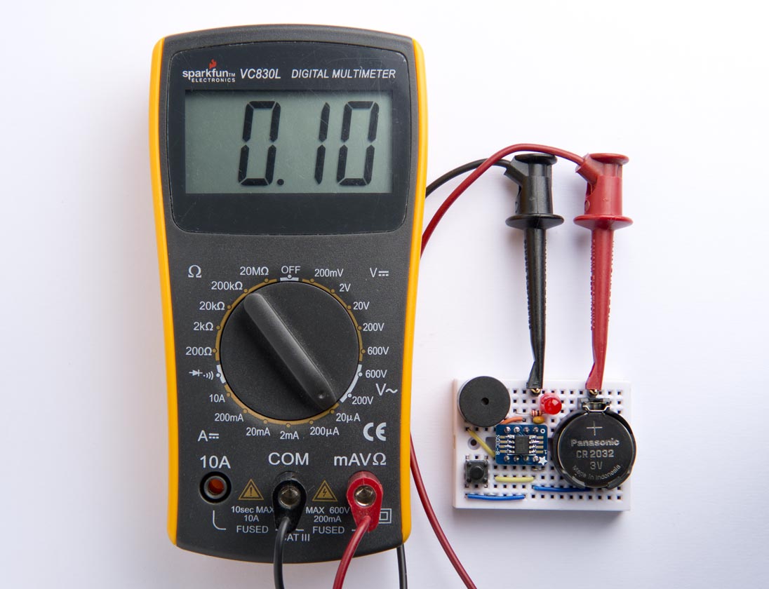
Measuring the current consumption of the ATtiny402 in sleep mode.
That's a theoretical battery life of over 200 years with a 200mAh CR2032 coin cell!
Comparison with the ATtiny85
To compare the ATtiny402 with the ATtiny85 I used in my original article ATtiny Low Power I built a version similar to the original circuit:
Circuit of the ATtiny85 version of the low power timer.
Here's the circuit built on a prototyping board:
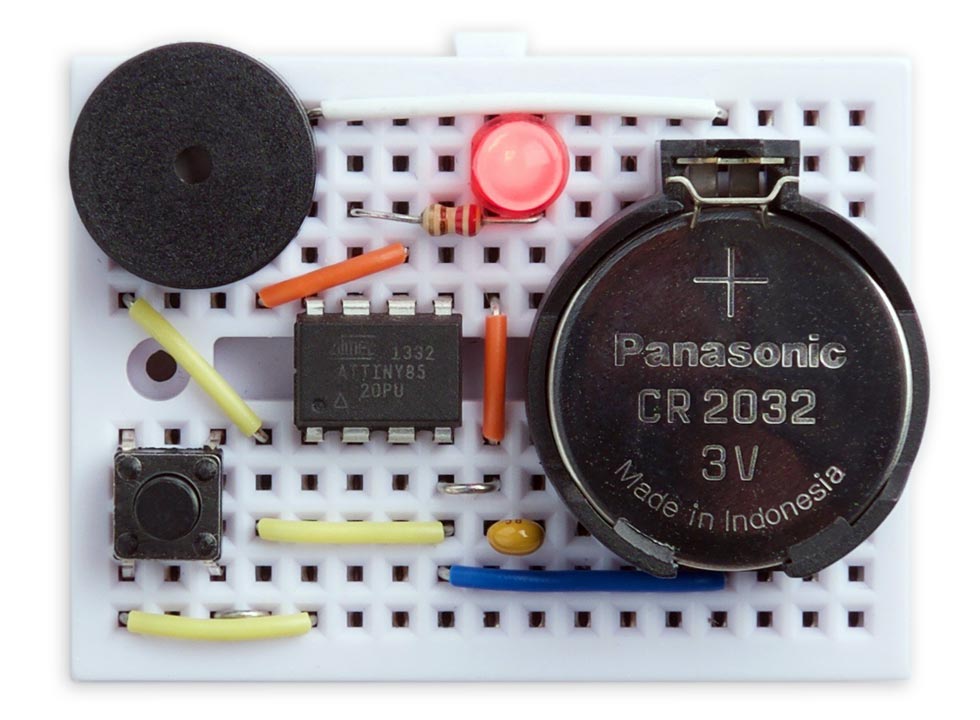
Prototype of the ATtiny85 version of the low power timer.
The following table showing the readings I obtained in sleep mode for each of the circuits, with my SparkFun Digital Multimeter [7] on the 20µA range, for supply voltages of 5v (from USB) and 3v from the coin cell:
| 5V | 3V | |
| ATtiny402 | 0.11µA | 0.10µA |
| ATtiny85 | 0.47µA | 0.17µA |
I also measured the sleep current consumption at 5V with my Nano Current Meter and got readings of 122nA for the ATtiny402 and 368nA for the ATtiny85, roughly in line with the above readings.
So the conclusion is that the ATtiny402 uses significantly lower current in sleep than its older cousin, the ATtiny85, especially at a 5V supply voltage.
Compiling the program
Compile the ATtiny402 program using Spence Konde's megaTiny Core on GitHub. Choose the ATtiny412/402/212/202 option under the megaTinyCore heading on the Board menu. Check that the subsequent options are set as follows (ignore any other options):
Chip: "ATtiny402"
Clock Speed: "5MHz"
Programmer: "jtag2updi (megaTinyCore)"
Then upload the program to the ATtiny402 using a UPDI programmer. You can make a UPDI programmer from an Arduino Uno, or other ATmega328P-based board, as described in Make UPDI Programmer.
You can ignore the error "Cannot locate flash and boot memories in description".
Here's the whole Low Power ATtiny402 program: Low Power ATtiny402 Program.
Here for comparison is the ATtiny85 version of the program: Low Power ATtiny85 Program.
- ^ SMT Breakout PCB for SOIC-8 on Adafruit.
- ^ Adafruit SMT breakout PCB for SOIC on Pimoroni.
- ^ SOIC8 to DIP8 Adapter Board on AliExpress.
- ^ Piezo Buzzer on Adafruit.
- ^ Breadboard - Mini Modular (White) on SparkFun.
- ^ Breadboard Mini Modular Self-Adhesive White on HobbyTronics.
- ^ Digital Multimeter - Basic on SparkFun.
blog comments powered by Disqus