Minimal ATSAMD21 Computer
12th March 2019
This project describes how to build an ATSAMD21-based computer on a prototyping board using the minimum number of components, and program it from the Arduino IDE:
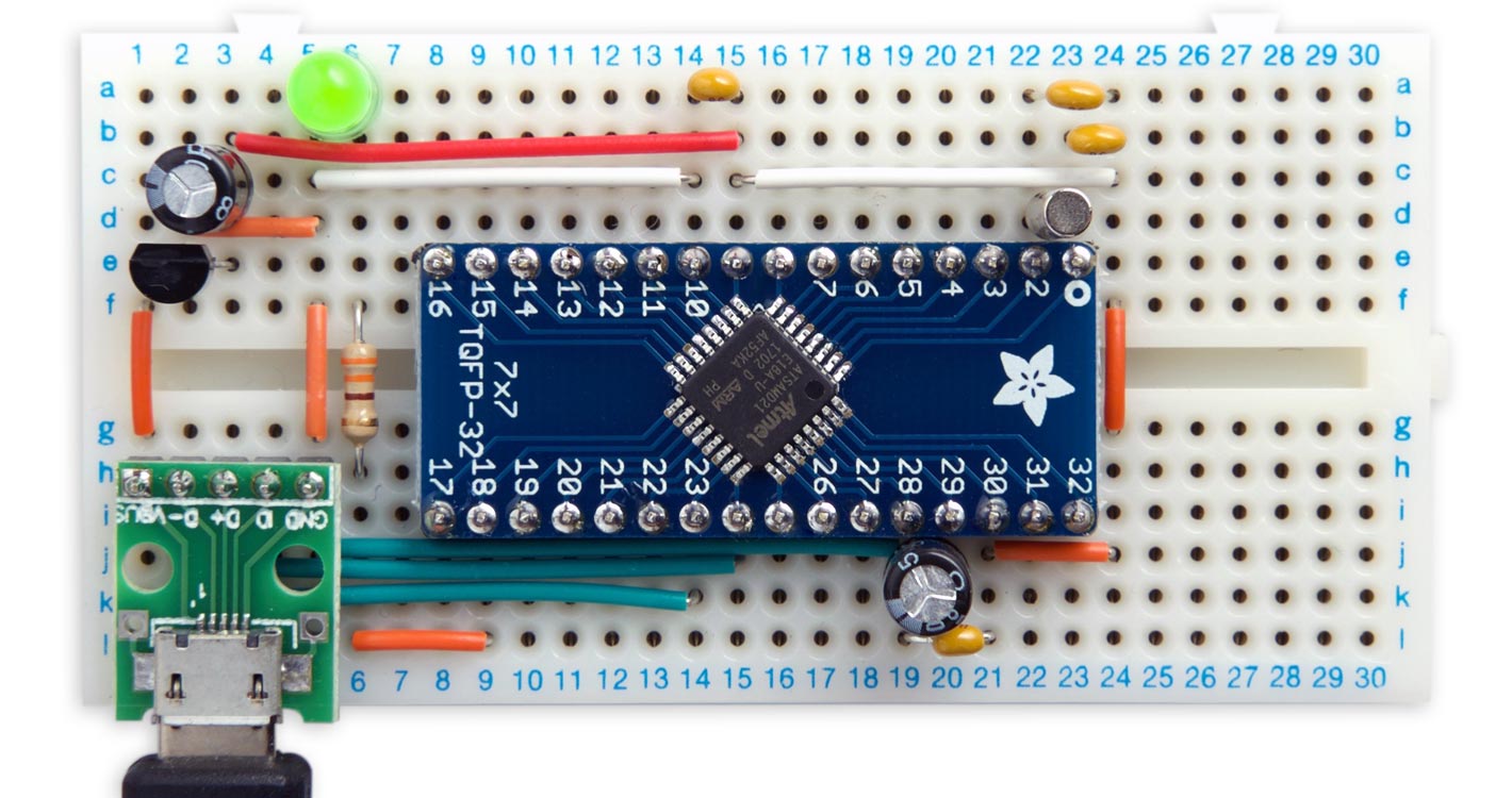
Minimal computer on a breadboard, based on an ATSAMD21E.
I give two alternative methods of uploading a bootloader to the bare ATSAMD21 chip using the Arduino IDE. You can then program the minimal ATSAMD21 computer from the Arduino IDE via the USB port, like any other Arduino board.
For details of the same procedure using the larger 48-pin ATSAMD21G chip see Minimal ATSAMD21 Computer 2.
Introduction
If you're looking for something more powerful than the ATmega328 in the Arduino Uno a good choice is the ATSAMD21. This is an ARM Cortex M0+ processor with up to 256KB flash memory, 32KB RAM, and a 48MHz clock, so it's substantially better equipped than the ATmega328. In addition it has a USB interface built in, so there's no need for a separate chip to interface to the serial port.
Arduino have designed several excellent boards based on the ATSAMD21, such as the Arduino Zero or smaller-format MKRZERO. However, these boards are an expensive way to use an ATSAMD21 as the basis for your own project, and they probably include many features you don't need.
In fact all you need to build an ATSAMD21-based computer on a prototyping board is:
- An ATSAMD21 processor on a breakout board.
- A USB socket on a breakout board.
- A 3.3V LDO regulator.
- A 32.768kHz crystal for the processor clock.
- Half a dozen decoupling and smoothing capacitors.
- An LED and resistor to let you verify that everything's working by running the Arduino Blink program.
I chose the smallest 32-pin variant of the ATSAMD21 with the maximum 256 KB flash memory and 32 KB RAM, the ATSAMD21E18A [1].
Installing a bootloader
If you want to be able to program the ATSAMD21 via the USB port, using the Arduino IDE, it's first necessary to install a bootloader in the chip to handle the USB to serial interface. One way to burn a bootloader into a bare ATSAMD21 is to use ATMEL Studio together with a programmer such as the Atmel ICE, or a JTAG programmer such as J-Link EDU.
Fortunately there are two easier ways that only require the Arduino IDE and another Arduino ATSAMD21 board:
- Using the Atmel Embedded Debugger (EDBG) on an Arduino Zero board.
- Using Debug Access Port (DAP) to install a file from an SD card using an ATSAMD21 board.
I describe both of these alternatives in detail below so you can choose the one that's easiest for you.
The circuit
Here's the circuit of the minimal ATSAMD21 computer:
Circuit of the minimal ATSAMD21 computer.
I mounted the ATSAMD21E on a breakout board from Adafruit [2]. The two capacitors each side of the crystal are supposed to connect to GND, but on the prototyping board it's easier to connect them to Vcc, which is equivalent to GND as far as a capacitor is concerned.
For the USB connector I used a USB Micro-B breakout board from Banggood [3]; a similar one is available from Adafruit [4].
The crystal was a cylindrical 32.768kHz watch crystal, such as the one available from SparkFun [5], and the regulator was an LE33 low dropout 3.3V regulator in a TO92 package, available from HobbyTronics in the UK [6].
I built the whole circuit on a 30x12 solderless breadboard from Rapid Online [7].
Testing the circuit
When you first connect power to the circuit I recommend monitoring the current consumption, as this will quickly give you an indication of whether there are any shorts or incorrect connections.
The expected current consumption at 3.3V is about 12mA. If you're getting much more than this, quickly disconnect the supply and check your wiring. If you're only getting around 0.3mA your crystal may not be oscillating; check the connections to the crystal and the crystal capacitors.
Uploading a bootloader using EDBG on an Arduino Zero board
This approach requires an Arduino/Genuino Zero [8]. This takes advantage of the fact that the Arduino/Genuino Zero includes the Atmel Embedded Debugger (EDBG), which implements an SWD interface that allows you to program a bare ATSAMD21. Thanks to Albert van Dalen for describing this procedure in his Avdweb blog [9].
Note that you can't use any ATSAMD21 board that doesn't include a USB Programming Port such as the MKRZERO, or Arduino Zero clones such as the Wemos SAMD21, because they don't have the integrated Atmel Embedded Debugger (EDBG).
Preparing the Arduino Zero board
To enable the Arduino Zero board to be used as a programmer we first need to remove two 0Ω resistors from the board, which by default link the EDBG debugger to the on-board ATSAMD21. These are R104 and R105 on the Arduino Zero circuit diagram [10].
Before removing the resistors you can verify that they are the correct ones by doing a continuity check with the SWDIO and SWCLK connections (pins 2 and 4) of the SWD connector at the right-hand edge of the board:
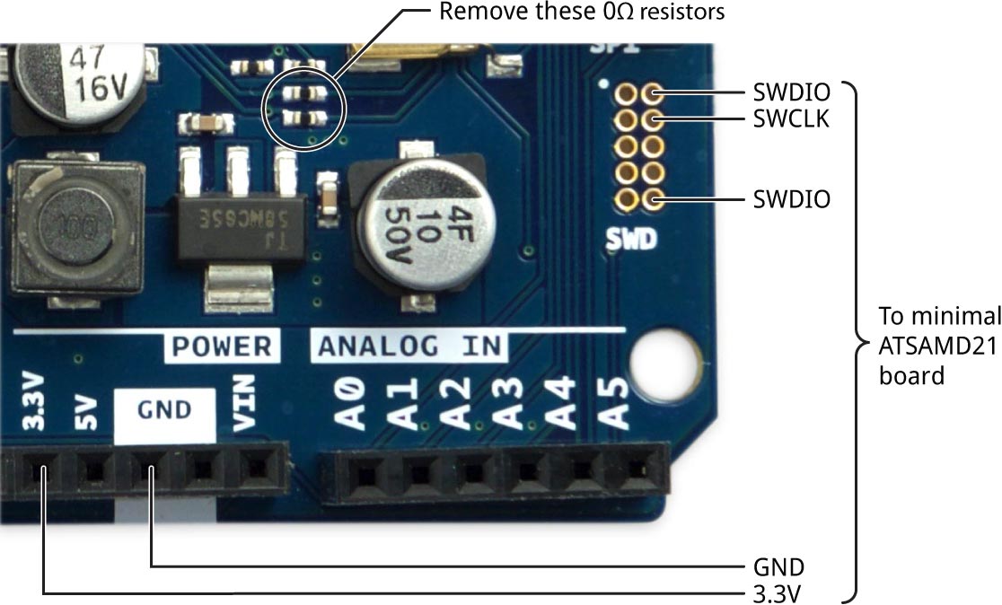
Using an Arduino Zero to upload a bootloader to the minimal ATSAMD21 computer.
To remove each resistor I carefully used a soldering iron with a flat bit to heat up both terminals of the resistor at the same time, and I then removed the resistor with a pair of tweezers.
Note that after removing these resistors you will only be able to upload programs via the Native USB port, although you will still be able to use the Programming USB port as a second serial port. If you want to reinstate the links at a later date you can just use two solder bridges between the pairs of pads.
Connecting the programming interface
- Connect the three signals from the SWD connector at the right-hand edge of the Arduino Zero, and the 3.3V and GND connectors from the headers, to the appropriate pins on your minimal ATSAMD21 board (see above diagram).
I used male-to-male jumper wires, which made a tight fit in the holes provided for the SWD connector; these are available from SparkFun [11], or HobbyTronics in the UK [12].
Uploading the bootloader
For this step the ATSAMD21D board will be powered from the Arduino Zero's power supply.
- Run the Arduino IDE on your computer.
- Select Arduino/Genuino Zero (Programming Port) from the Board submenu on the Tools menu.
- Select Atmel EDBG from the Programmer submenu on the Tools menu.
- Connect the PROGRAMMING+EDBG USB socket on the Arduino to your computer's USB port.
- Select the portport identified as the USB port from the Port submenu on the Tools menu.
- Choose Burn Bootloader from the Tools menu.
This burns the standard bootloader samd21_sam_ba.bin from your Arduino SAMD installation.
If all is well you should see messages in the Arduino IDE window ending with:
** Programming Finished **
** Verify Started **
verified 6504 bytes in 0.567837s (11.186 KiB/s)
** Verified OK **
** Resetting Target **
shutdown command invoked
You have now installed a bootloader in the ATSAMD21 on your board!
Uploading a bootloader from an SD card using DAP
This alternative approach requires an ATSAMD21 board with an SD card interface. In the following description I'll assume you're using an MKRZERO, but it could be any other ATSAMD21 board with an SD card socket or an SD card shield.
Installing the DAP library
This method uses Adafruit's Adafruit_DAP (Debug Access Port) code. Thanks to Dean Miller for his tutorial on the Adafruit site [13].
- Download the Adafruit DAP library from GitHub: Adafruit DAP library
- Copy the Adafruit_DAP-master folder to your Arduino libraries folder.
Preparing the bootloader file
- Find the bootloader binary file samd21_sam_ba.bin.
It should be located in your Arduino SAMD installation in the folder:
arduino/hardware/samd/1.6.20/bootloaders/zero/
where 1.6.20 depends on the version number of your Arduino SAMD Boards installation.
- Using your computer, rename the binary file samd21_sam_ba.bin to fw.bin and copy it to an SD card.
- Insert the SD card in the SD socket on your MKRZERO.
Connecting the programming interface
- Connect the following pins from the headers on the MKRZERO to the appropriate pins on your minimal ATSAMD21 board:
| MKZERO pin | ATSAMD21 pin |
| 9 | SWCLK |
| 10 | SWDIO |
| 11 | RESET |
| GND | GND |
| VCC | 3.3V |
Uploading the bootloader
- Run the Arduino IDE on your computer.
- In the Arduino IDE open the example flash_from_SD from File, Examples, Adafruit DAP library.
- In the file edit the #define SD_CS to suit the SD card interface you're using. For the MKRZERO it should be set to 28.
- Connect the USB socket on the MKRZERO to your computer's USB port.
- Upload the flash_from_SD program to your MKRZERO.
- Open the Serial Monitor in the Arduino IDE.
The program should run and the following text will be displayed:
Card initialized
Connecting...Adafruit Generic CMSIS-DAP Adapter 123456 v0.1 (S)

Found Target: SAM D21E18A	Flash size: 262144	Flash pages: 4096
 done.
Erasing...  done.
Programming... 66

Done!
You have now installed a bootloader in the ATSAMD21 on your board!
Arduino pin assignments
Using the Arduino/Genuino Zero (Native USB Port) board setting the ATSAMD21E pins will map to the Arduino core functions as shown in the following diagram:
Pins marked '~' can be used with analogWrite().
Uploading a program via USB
The next step is to try uploading a program to the minimal ATSAMD21 computer via the USB port.
- Select Arduino/Genuino Zero (Native USB Port) from the Board submenu on the Tools menu.
- Connect the USB port on your ATSAMD21 board to a USB port on your computer.
- Select the port identified as the USB port from the Port submenu on the Tools menu.
If the port doesn't appear there may be a problem with the USB connection on your prototyping board, or the crystal oscillator, in which case check your wiring.
Upload the Blink example
The first thing to try with any new Arduino project is the Blink example.
- Open the Blink program from File, Examples, 01:Basics.
- Choose Upload from the Sketch menu.
If the upload succeeds you should see your LED blinking on the minimal ATSAMD21 board.
Upload uLisp
As a more demanding test you might like to try running the ARM version of my Lisp interpreter, uLisp, on the minimal ATSAMD21 board. Download it here: Download uLisp
In the Arduino/Genuino Zero board definition the native USB port is called SerialUSB, so before uploading uLisp add the following line at the beginning of the file (or the Serial Monitor won't work):
#define Serial SerialUSB
Here's the uLisp equivalent of the Blink program; type it into the Serial Monitor:
(loop (pinmode 13 t) (digitalwrite 13 (not (digitalread 13))) (delay 1000))
The Benchmarks running on the minimal ATSAMD21 board give the same timings as an Arduino MKRZERO board.
- ^ ATSAMD21E18A-AU on Farnell.
- ^ SMT Breakout PCB for 32-QFN or 32-TQFP on Adafruit.
- ^ Micro USB to Dip Female Socket B Type on Banggood.
- ^ USB Micro-B Breakout Board on Adafruit.
- ^ Crystal 32kHz on SparkFun.
- ^ 3.3V Low dropout Voltage Regulator 100mA LE33CZ on HobbyTronics.
- ^ AD-100 Advanced Solderless Breadboard - 360 Tie Points on Rapid Online.
- ^ Genuino Zero on Arduino Store.
- ^ How to burn/flash a bootloader into an external ATSAMD21 on Avdweb.
- ^ Arduino Zero schematic on Arduino.cc.
- ^ Jumper Wires Premium 6" on SparkFun.
- ^ Jumper Wires Premium 6in on HobbyTronics.
- ^ Programming an M0 using an Arduino on Adafruit.
blog comments powered by Disqus