ATtiny85 20MHz Internal Clock
24th May 2018
The ATtiny85 is rated at a maximum clock speed of 20MHz at 4.5 – 5.5V. For some applications it would be nice to get the maximum speed without needing to buy a 20MHz crystal, or tie up two I/O lines driving the crystal. Here's how to do it.
To test it I toggled an output at the clock frequency, and measured it with a frequency meter:
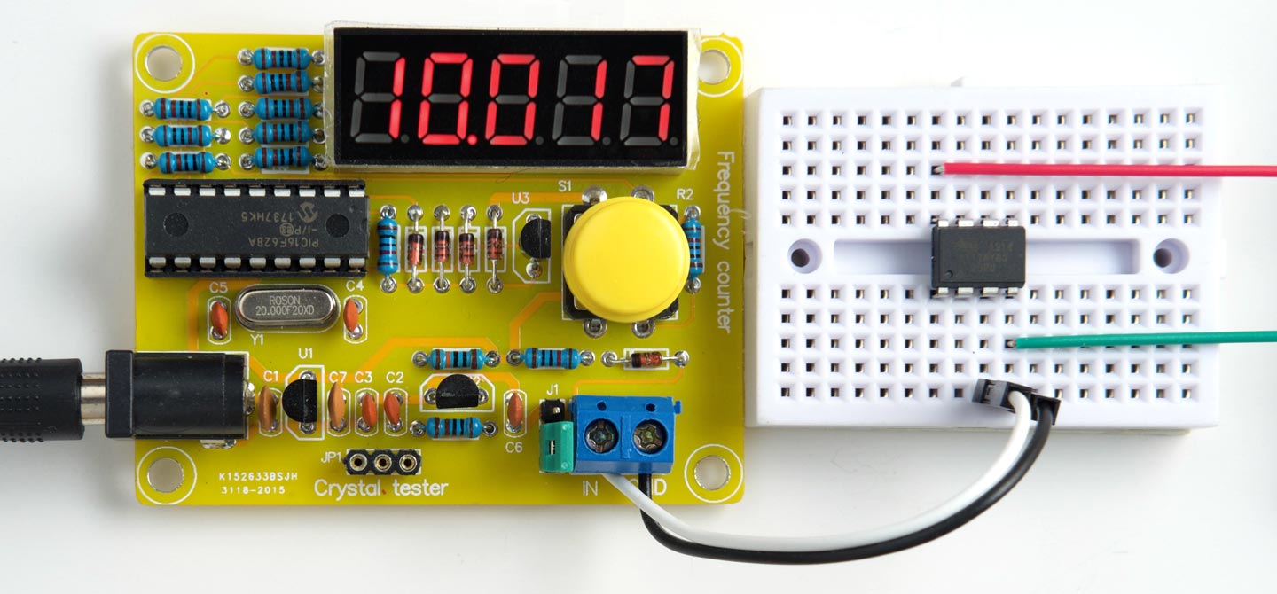
Measuring half the clock frequency of an ATtiny85 running at 20MHz.
The reading of 10MHz implies a clock frequency of 20MHz.
Introduction
The ATtiny85 is almost unique among the AVR chips in having an internal PLL (Phase-Locked Loop) that can multiply up the internal 8MHz clock by a factor of 8 to 64MHz, for use by Timer/Counter1. By programming a fuse you can choose to use the PLL divided by four as the system clock, giving a clock speed of 16MHz.
Looking at the ATtiny85 datasheet we see that there's an OSCCAL register that allows you to adjust the internal clock frequency to between almost -50% and +100%:
Effect of OSCCAL calibration on the internal oscillator, from the ATtiny85 datasheet.
Thus, by choosing an OSCCAL value of about 192 we can increase the internal clock from 8MHz to 10MHz, and this will give a system clock derived from the PLL of 20MHz.
Testing
To test the 20MHz internal clock I set up Timer/Counter1 to toggle the OC1B output (PB4) at the clock frequency, giving a square wave of half the clock frequency:
void setup() {
  OSCCAL = 181;
  TCCR1 = 1<<CTC1 | 0<<COM1A0 | 1<<CS10; // CTC mode, /1
  GTCCR = 1<<COM1B0;                     // Toggle OC1B
  PLLCSR = 0<<PCKE;                      // System clock as clock source
  OCR1C = 0;
  pinMode(4, OUTPUT);
}
I powered the ATtiny85 from 5V and measured the frequency with a Geekcreit Frequency Tester. It's available on Banggood for under £10/$10 [1].
Compile the program using Spence Konde's ATTiny Core [2]. Choose the ATtiny25/45/85 option under the ATtinyCore heading on the Board menu. Then choose Timer 1 Clock: CPU, B.O.D. Disabled, ATtiny85, 16 MHz (PLL) from the subsequent menus. Choose Burn Bootloader to set the fuses appropriately. Then upload the program using ISP (in-system programming); I used Sparkfun's Tiny AVR Programmer Board; see ATtiny-Based Beginner's Kit.
With the correct OSCCAL value that gives a 20MHz system clock this should produce an output of 10MHz on PB4. I found the value 181 gave the closest value.
Overclocking
The datasheet states that "the fast peripheral clock will saturate ... at about 85MHz". This means that we can expect to achieve a maximum system clock speed of 85/4 or 21.25MHz by adjusting OSCCAL. In practice I found I could go higher than this.
Other AVR chips
Two other AVR chips include a PLL: the ATtiny861, and the ATmega32u4, and it should be possible to use the same technique with these chips to provide a 20MHz internal clock.
- ^ Geekcreit DIY Frequency Tester 1Hz-50MHz Crystal Counter Meter With Housing Kit on Banggood.
- ^ ATTinyCore on GitHub.
blog comments powered by Disqus