Digital Clock Using Lisp
7th July 2016
This article describes a digital clock based on an ATmega328, using an I2C four-digit seven-segment display, and an I2C real-time clock module for the timekeeping. So far nothing unusual about that; except that the clock is programmed in Lisp, using my uLisp interpreter for the Arduino:
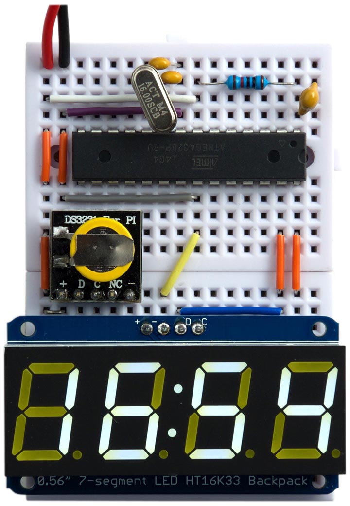
Clock based on an ATmega328, I2C display, and RTC module, programmed in uLisp.
Circuit
Here's the full circuit for the Lisp Clock:
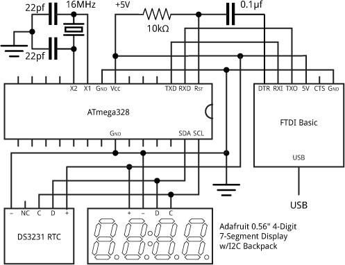
Circuit for the clock programmed in uLisp.
The processor is an ATmega328P running at 16 MHz, with a 16 MHz crystal to generate the clock. The processor clock isn't used for timekeeping, so a ceramic resonator would probably be adequate.
The timekeeping is provided by an DS3231 RTC module [1], which is a low-cost, extremely accurate I2C real-time clock with an integrated temperature-compensated crystal oscillator. Boards are available from several suppliers; I used one incorporating a backup battery from Seeed Studio [2], available from The Pi Hut in the UK [3]. I swapped the header socket for a row of header pins to make it easier to fit it into the breadboard.
For the display I used an I2C 7-segment display from Adafruit [4]. I chose a white display, but it's available in a range of other colours.
The modules connect to the ATmega328 using four wires: Data to SDA (pin 27), Clock to SCL (pin 28), VCC, and GND. I used the default I2C address for each device; #x70 for the RTC, and #x68 for the display.
I built the circuit on a pair of mini breadboards, available from SparkFun [5] or HobbyTronics in the UK [6]. I powered the clock from a 3.7V LIPO cell.
Installing a bootloader
Unless you bought an ATmega328 chip with a bootloader already installed, you'll first need to upload a bootloader using In-System Programming (ISP). I used Sparkfun's Tiny AVR Programmer, as described in ATtiny-Based Beginner's Kit. Connect the Tiny AVR Programmer to the SCK, MISO, MOSI, RESET, VCC, and GND pins on the ATmega328, select Arduino/Genuino Uno on the Board submenu, and choose Burn Bootloader from the Arduino IDE Tools menu.
Communicating with the ATmega328
To upload the uLisp interpreter to the ATmega328, and then program the clock in Lisp, you will need an FTDI USB-to-serial converter. There are several alternatives available; I used the FTDI Basic Breakout from Sparkfun [7], available from HobbyTronics in the UK [8]. Connect the FTDI board to the RXD, TXD, RESET, VCC, and GND pins on the ATmega328:
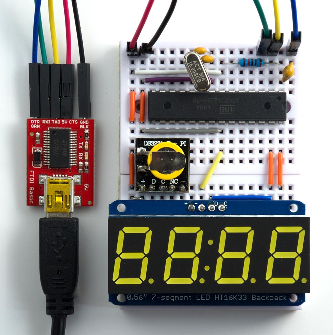
Connecting the clock to the Arduino IDE via an FTDI USB-to-serial converter.
The first step is to install the uLisp interpreter. Get the latest version from the Download uLisp page, and upload it to the ATmega328 from the Arduino IDE. From now on you can program the clock in Lisp using the Serial Monitor in the Arduino IDE; for more information see Using uLisp.
Setting the time
The next step is to set the RTC to the correct time. To do this, define the following routine from the Serial Monitor:
(defun set (hr min)
  (with-i2c (str #x68)
    (write-byte 0 str)
    (write-byte 0 str)
    (write-byte min str)
    (write-byte hr str)))
The first call to write-byte sets the starting register to write to in the DS3231; in this case 0, the seconds register. We then set the seconds to 0, the minutes to min, and the hours to hr. The times are defined in binary-coded decimal, so to set the time to 12:34 you need to evaluate:
(set #x12 #x34)
Once you have set the time the backup battery will keep the time correct in the DS3231, and so you should remove the set routine from memory to save space with the command:
(makunbound 'set)
The clock program
The next step is to define the clock program in Lisp. First we define the seven-segment display patterns for the digits 0 to 9:
(defvar seg '(#x3F #x06 #x5B #x4F #x66 #x6D #x7D #x07 #x7F #x6F))
Next the routine go initialises the display and sets the brightness to 1:
(defun go ()
  (with-i2c (str #x70)
    (write-byte #x21 str)
    (restart-i2c str)
    (write-byte #x81 str)
    (restart-i2c str)
    (write-byte #xe1 str)))
The last write-byte sets the brightness, which can be from #xe0 (off) to #xef (maximum).
Finally, here's the main clock program, clk:
(defun clk ()
  (let ((col 2) hr min)
    (go)
    (loop

     ;; Read the time from the RTC
     (with-i2c (str #x68)
       (write-byte 1 str)
       (restart-i2c str 2)
       (setq min (read-byte str))
       (setq hr (read-byte str)))

     ;; Write the time to the display
     (with-i2c (str #x70)
       (write-byte 0 str)
       (dolist (c (list
                   (nth (/ hr 16) seg)
                   (nth (mod hr 16) seg)
                   col
                   (nth (/ min 16) seg)
                   (nth (mod min 16) seg)))
         (write-byte c str)
         (write-byte 0 str)))

     ;; Flash the colon
     (setq col (- 2 col))
     (delay 1000))))
For each display digit you have to write two bytes to the display; this is for compatibility with Adafruit's other displays, and for this display the second byte is always zero. Curiously, there are effectively five digits, with the colon counted as the third digit, and to light it you have to write the value 2.
Making a stand-alone application
If you want the clock to run automatically when you connect power to the Arduino, save the image with:
(save-image 'clk)
You now have a stand-alone digital clock programmed in Lisp!
Extensions
The DS3231 RTC includes the date, and two alarms, and the uLisp program could easily be extended to interface with these. However, the above clock program only just fits in the 2 Kbytes of RAM available in the ATmega328, so you would need a processor with more RAM.
Unfortunately Atmel don't make another processor in the ATmega328 series (an “ATmega648” would be nice with 4 Kbytes of RAM). However, the ATmega644 and ATmega1284 provide 4 Kbytes and 16 Kbytes of RAM respectively, and they're available in PDIP packages, so either of these would be suitable. I hope to write about using these in a future article.
- ^ DS3231 Datasheet on Maxim Integrated.
- ^ Mini RTC Module on Seeed Studio.
- ^ Mini RTC Module for Raspberry Pi on The Pi Hut.
- ^ Adafruit 0.56" 4-Digit 7-Segment Display w/I2C Backpack on Adafruit.
- ^ Breadboard - Mini Modular on SparkFun.
- ^ Mini Breadboard from HobbyTronics.
- ^ FTDI Basic Breakout on Sparkfun.
- ^ FTDI Basic Breakout on HobbyTronics.
blog comments powered by Disqus