Tiny TFT Graphics Library
13th June 2019
This is a graphics library for the family of small colour TFT displays based on the ST7735 and ST7789 driver chips. These are really nice displays; bright, colourful, available in a variety of useful sizes, and available at low cost from suppliers like Adafruit, AliExpress, or Banggood:

Tiny TFT Graphics Library running on a 160x80 TFT display from AliExpress.
This library allows you to plot points, draw lines, draw filled rectangles, and plot text with an optional scale factor. I've included a demo histogram-plotting program that adjusts itself to fit each of the displays I've supported.
Unlike most other TFT display libraries this one doesn't require a memory buffer, allowing it to be run on any processor down to an ATtiny85. The displays are SPI and require four pins to drive the display, leaving one pin free on an ATtiny85 to interface to another device, such as a temperature sensor. If you need more pins choose a larger chip, such as the ATtiny84; see Using the library with other AVR chips at the end of the article for information about how to convert the code for different chips.
Note that there is an improved version of this library with support for more displays; see Tiny TFT Graphics Library 2.
For a version of this library that works with any processor that has SPI, and supports additional displays, see Compact TFT Graphics Library.
Introduction
I started developing this library for another project that I hope to write about at a later date; in the meantime I thought it would be useful to write it up as a stand-alone article.
I've published a library for a colour OLED display in a previous article: Colour Graphics Library. The main difference between the colour TFT displays and the colour OLED displays is that the TFT displays are not self-illuminating, and so need a backlight; they therefore have a slightly higher power consumption. However, they are exceedingly cheap, and they are available in larger sizes than the colour OLED displays.
I wrote an initial version of this library in uLisp, my Lisp interpreter for microcontrollers, which made it easy to experiment with different approaches. I then converted it to C to run on an ATtiny85. I can publish the uLisp version if anyone's interested.
Supported displays
This library will work with displays based on the ST7735 which supports a maximum display size of 132 (H) x 162 (V), or the similar ST7789 which supports a maximum display size of 240 (H) x 320 (V).
I've tested it with the following display boards:
Adafruit 160x80
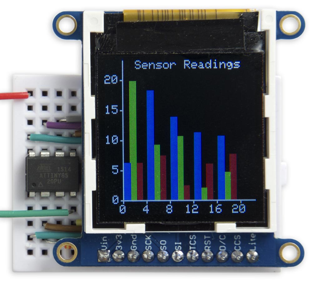
This is a 0.96" 80x160 Colour TFT display from Adafruit [1]: or The Pi Hut in the UK [2].

Tiny TFT Graphics Library running on an Adafruit 160x80 TFT display.
A similar display is available from AliExpress [3], shown in the photograph at the beginning of this article, but note that this one is 3.3V only.
Adafruit 128x128
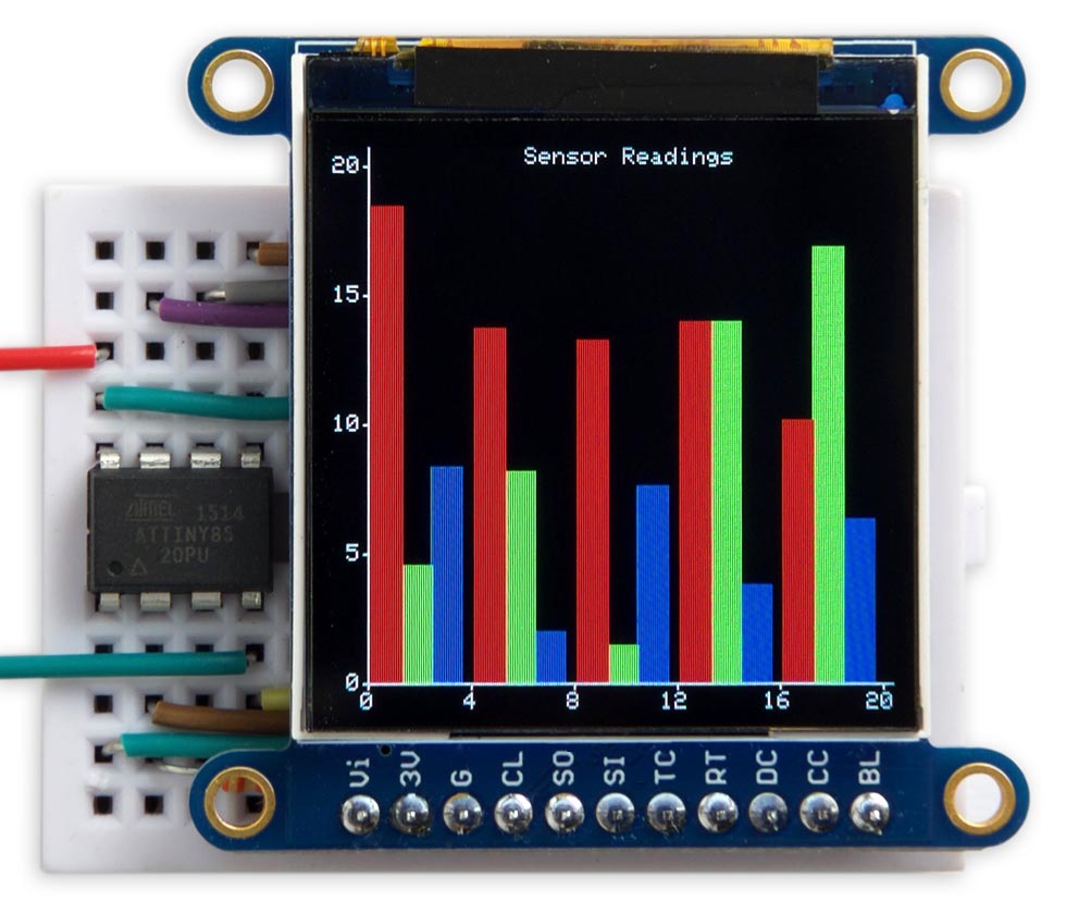
This is a 1.44" 128x128 Colour TFT display from Adafruit [4]:
Tiny TFT Graphics Library running on an Adafruit 128x128 TFT display.
Adafruit 160x128
This is a 1.8" 160x128 Colour TFT from Adafruit [5] or The Pi Hut in the UK [6].
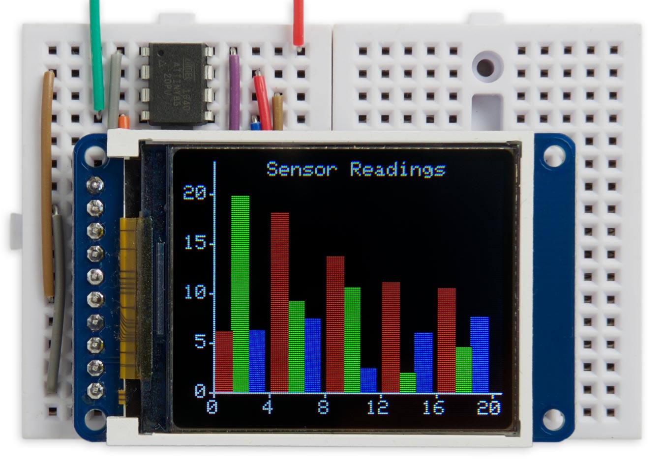
Tiny TFT Graphics Library running on an Adafruit 160x128 TFT display.
A similar display is available from AliExpress [7].
Adafruit 240x240
This is a 1.54" 240x240 Colour TFT from Adafruit [8] or from Pimoroni in the UK [9]:
Tiny TFT Graphics Library running on an Adafruit 240x240 TFT display.
The same settings also work with the Adafruit 1.3" 240x240 TFT display [10]. which conveniently has the same pinout.
Notes
The display driver interfaces to the displays with the longer side as the vertical dimension, which is why the rectangular displays are usually listed with the longer dimension second. My library allows you to rotate the image for any desired orientation.
All the Adafruit breakout boards for these displays include level-shifting circuitry, so they will work with either 5V or 3.3V microcontroller boards. They also include an SD card socket, if that's of interest to you. The Adafruit boards have pullups on the backlight and reset pins, so the display will work if you leave these pins unconnected.
The boards available from AliExpress or Banggood are generally 3.3V only. If you're using them with a 5V microcontroller you need to include a regulator and level-shifting circuitry.
The circuit
Here's the circuit:
Circuit of the TFT colour graphics display interface based on an ATtiny85.
The pullup resistor from the display's CS pin is optional; it holds the chip select high to prevent the display from being affected by the ISP signals while programming the ATtiny85.
On the 160x128 displays you need to connect the backlight pin to Vcc to turn it on. This doesn't seem to be necessary with the other displays.
Note that on different display boards the pins are labelled in a variety of ways:
| Pin | Labelled |
| Vcc | Vin |
| Ground | GND |
| Clock | SCK, SCL |
| Data In | MOSI, SI, SDA |
| Chip Select | CS, TCS |
| Data/Command | DC, D/C, A0 |
| Backlight | LITE, LIT, BLK |
Don't be confused by pins labelled SCL and SDA on some displays; these are all definitely SPI displays!
The program
Defining the display
The different displays are catered for by six constants which specify the size of the display, the offsets relative to the area supported by the display driver, whether the display is inverted, and the rotation value; for example:
// Adafruit 0.96" 80x160 display
int const ysize = 80, xsize = 160, yoff = 24, xoff = 0, invert = 0, rotate = 0;
Uncomment the parameters for the display you're using.
The display driver allows you to rotate the display into any orientation, specified by the value of the constant rotate:
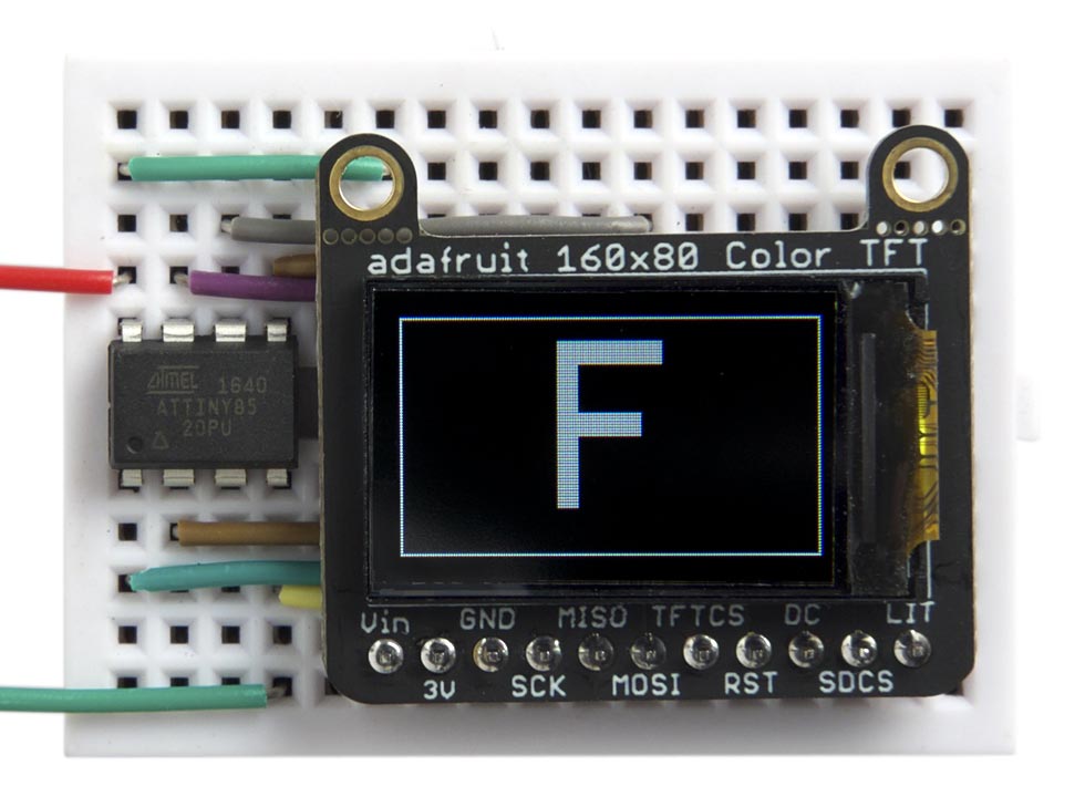
Test pattern displayed on an Adafruit 160x80 TFT display.
This gives you the freedom to mount the display in whatever orientation you prefer.
Note that on some displays you may also have to change the xoff or yoff value when rotating the display. For example, to rotate the image on the 240x240 displays by 180° use the settings:
int const ysize = 240, xsize = 240, yoff = 80, xoff = 0, invert = 1, rotate = 5;
To check or adjust the values for each display I ran this program, which draws a one-pixel border around the display area, and plots an "F" to show the orientation:
void TestChart () {
  MoveTo(0,0);
  DrawTo(xsize-1, 0); DrawTo(xsize-1, ysize-1);
  DrawTo(0, ysize-1); DrawTo(0, 0);
  scale=8;
  MoveTo((xsize-40)/2, (ysize-64)/2); PlotChar('F');
  for(;;);
}
For example:
You can use this to find the correct parameters for a new display that I haven't included here.
Writing to the display
The ATtiny85 and other AVR processors supports toggling of one or more bits in a port, so provided you set all the pins to their disabled state at startup, for speed the display access routines can simply toggle the appropriate pins to enable or disable them.
The Data() routine sends a byte to the display by toggling the clock pin, sck, for each bit on the mosi pin:
void Data (uint8_t d) {
  for (uint8_t bit = 0x80; bit; bit >>= 1) {
    PINB = 1<<sck;                        // sck low
    if (d & bit) PORTB = PORTB | (1<<mosi); else PORTB = PORTB & ~(1<<mosi);
    PINB = 1<<sck;                        // sck high
  }
}
This approach seems to be faster than using the Arduino core's SPI routines.
Before and after accessing the display you need to toggle the chip-select pin, cs, with the statement:
PINB = 1<<cs;
Writing a command
To send a command byte you need to toggle the DC bit low:
void Command (uint8_t c) {
    PINB = 1<<dc;                           // dc low
    Data(c);
    PINB = 1<<dc;                           // dc high again
}
Several commands take two data words as parameters; the Command2() routine provides a convenient way of dealing with these:
void Command2 (uint8_t c, uint16_t d1, uint16_t d2) {
    PINB = 1<<dc;                          // dc low
    Data(c);
    PINB = 1<<dc;                          // dc high again
    Data(d1>>8); Data(d1); Data(d2>>8); Data(d2);
}
Initialising the display
The InitDisplay() routine first defines the four display pins as outputs, and takes the SCK, DC, and CS pins high (inactive). It then sends the essential configuration commands to the display.
Most published ST7735 libraries have a long list of initialisation parameters, but I found that most of these aren't necessary, as the default settings work fine, and I've whittled the list down to just five commands:
void InitDisplay () {
  DDRB = 1<<dc | 1<<cs | 1<<mosi | 1<<sck; // All outputs
  PORTB = 1<<sck | 1<<cs | 1<<dc;          // clk, dc, and cs high
  PINB = 1<<cs;                            // cs low
  Command(0x01);                           // Software reset
  delay(150);                              // delay 150 ms
  Command(0x11);                           // Out of sleep mode
  delay(500);                              // delay 500 ms
  Command(0x3A); Data(0x05);               // Set color mode - 16-bit color
  Command(0x20+invert);                    // Invert
  Command(0x36); Data(rotate<<5);          // Set orientation
  PINB = 1<<cs;                            // cs high
}
Colours
The display memory stores 18 bits per pixel: 6 bits per colour. However, you can write to the display in three alternative modes, with 12, 16, or 18 bits per pixel. I chose the 16 bit mode, which assigns 5 bits to red, 6 bits to green, and 5 bits blue. It's the most convenient one to work with as you simply send two bytes to define the colour of each pixel.
The foreground and background colours are defined by the two global variables fore and back. Initially these are set to 0xFFFF, white, and 0, black, respectively:
int fore = 0xFFFF; // White
int back = 0;      // Black
The routine Colour lets you create a colour value by specifying its red, green, and blue components as numbers from 0 to 255:
unsigned int Colour (int r, int g, int b) {
  return (r & 0xf8)<<8 | (g & 0xfc)<<3 | b>>3;
}
Clearing the display
To clear the display the ClearDisplay() routine sends the appropriate number of zero bytes. The routine temporarily switches to 12-bit colour mode, which reduces the time to clear the display by 25%:
void ClearDisplay () {
  PINB = 1<<cs;                            // cs low
  Command2(CASET, yoff, yoff + ysize - 1);
  Command2(RASET, xoff, xoff + xsize - 1);
  Command(0x3A); Data(0x03);               // 12-bit colour
  Command(RAMWR);
  for (int i=0; i<xsize/2; i++) {
    for (int j=0; j<ysize * 3; j++) {
      Data(0);
    }
  }
  Command(0x3A); Data(0x05);               // Back to 16-bit colour
  PINB = 1<<cs;                            // cs high
}
Plotting points and drawing lines
The library includes basic graphics routines for plotting points and drawing lines. These work on a conventional coordinate system with the origin at lower left. For example, on the 80x160 display:
The current drawing position is stored in the global variables x0 and y0. You can change this with the MoveTo() command:
void MoveTo (int x, int y) {
  x0 = x; y0 = y;
}
The PlotPoint() routine plots a single point in the current foreground colour:
void PlotPoint (int x, int y) {
  PINB = 1<<cs;                            // cs low
  Command2(CASET, yoff+y, yoff+y);
  Command2(RASET, xoff+x, xoff+x);
  Command(RAMWR); Data(fore>>8); Data(fore & 0xff);
  PINB = 1<<cs;                            // cs high
}
It works by defining the addressing area to be one pixel, and then sends the foreground colour as two bytes of data.
The DrawTo() line-drawing routine uses Bresenham's line algorithm to draw the best line between two points without needing any divisions or multiplications [11]:
void DrawTo (int x, int y) {
  int sx, sy, e2, err;
  int dx = abs(x - x0);
  int dy = abs(y - y0);
  if (x0 < x) sx = 1; else sx = -1;
  if (y0 < y) sy = 1; else sy = -1;
  err = dx - dy;
  for (;;) {
    PlotPoint(x0, y0);
    if (x0==x && y0==y) return;
    e2 = err<<1;
    if (e2 > -dy) { err = err - dy; x0 = x0 + sx; }
    if (e2 < dx) { err = err + dx; y0 = y0 + sy; }
  }
}
It calls PlotPoint() to plot the points.
Drawing rectangles
The FillRect() routine draws a filled rectangle at the current drawing position in the foreground colour:
void FillRect (int w, int h) {
  PINB = 1<<cs;                            // cs low
  Command2(CASET, y0+yoff, y0+yoff+h-1);
  Command2(RASET, x0+xoff, x0+xoff+w-1);
  Command(RAMWR);
  for (int p=0; p<w*h*2; p++) {
    Data(fore>>8); Data(fore & 0xff);
  }
  PINB = 1<<cs;                            // cs high
}
The parameters w and h specify the width and height of the rectangle.
Characters and text
The character set is defined by data stored in program memory. An abbreviated version of the character map is as follows:
const uint8_t CharMap[96][6] PROGMEM = {
{ 0x00, 0x00, 0x00, 0x00, 0x00, 0x00 },
{ 0x00, 0x00, 0x5F, 0x00, 0x00, 0x00 },
...
{ 0xFF, 0xFF, 0xFF, 0xFF, 0xFF, 0x00 }
};
The first row defines the bit patterns for ASCII character 32, space, and so on up to character 127.
The PlotChar() routine plots a specified character at the current plot position, and in the current foreground colour.
My first version of PlotChar() plotted characters by calling PlotPoint() for each pixel. However, I then tried the following alternative approach which defines an area of the display using the CASET (Column Address Set) and RASET (Row Address Set) commands, and then sends a stream of the appropriate bytes to define the character. This turned out to be over three times faster!
void PlotChar (char c) {
  int colour;
  PINB = 1<<cs;                            // cs low
  Command2(CASET, yoff+y0, yoff+y0+8*scale-1);
  Command2(RASET, xoff+x0, xoff+x0+6*scale-1);
  Command(RAMWR);
  for (int xx=0; xx<6; xx++) {
    int bits = pgm_read_byte(&CharMap[c-32][xx]);
    for (int xr=0; xr<scale; xr++) {
      for (int yy=0; yy<8; yy++) {
        if (bits>>(7-yy) & 1) colour = fore; else colour = back;
        for (int yr=0; yr<scale; yr++) {
          Data(colour>>8); Data(colour & 0xFF);
        }
      }
    }
  }
  PINB = 1<<cs;                            // cs high
  x0 = x0 + 6*scale;
}
The default value of scale is 1, but you can change it to plot larger characters. After plotting a character PlotChar() moves the plot position to the start of the next character to make it easy to plot several characters in a row without needing to call MoveTo().
Finally PlotText() allows you to plot text from a string in program memory:
void PlotText(PGM_P p) {
  while (1) {
    char c = pgm_read_byte(p++);
    if (c == 0) return;
    PlotChar(c);
  }
}
To define the text to be plotted as being in program memory use the PSTR() macro (for program string); for example:
PlotText(PSTR("Graphics Display"));
Demo program
The demo program, in loop(), plots the histogram shown in the photographs. It automatically scales itself to the dimensions of the current display.
Compiling the program
I compiled the program using Spence Konde's ATTiny Core [12]. Choose the ATtiny25/45/85 option under the ATTinyCore heading on the Board menu. Then check that the subsequent options are set as follows (ignore any other options):
Chip: "ATtiny85"
Clock: "8 MHz (internal)"
B.O.D: "B.O.D. Disabled"
Timer 1 Clock: "CPU"
By default the ATtiny85 runs at 1MHz. Choose Burn Bootloader to set the fuses for 8MHz operation, or your graphics will run rather slowly, then upload the program using ISP (in-system programming).
If your display is a 5V board you could use Sparkfun's Tiny AVR Programmer Board [13]. If your display only supports a 3.3V supply make sure your programmer has a 3.3V option, such as USBasp [14], widely available on eBay.
Here's the Tiny TFT Graphics Library program with the example used for the photos in the article: Tiny TFT Graphics Library Program.
Using the library with other AVR chips
Here are some suggestions for converting this library for use with another AVR processor:
- Choose which pins you want to use for dc, mosi, sck, and cs; they should all be in the same port.
For example on the ATtiny84 choose PORTA.
- Change the definitions of dc, mosi, sck, and cs to correspond to the bit positions of the pins in that port.
For example, if you chose PA4 for sck change the definition to:
int const sck = 4;
- Change all occurrences of PORTB, PINB, and DDRB in the listing to the appropriate values for the port you're using.
For example, on the ATtiny84 change them to PORTA, PINA, and DDRA.
Updates
14th June 2019: Added a photograph of the Adafruit 1.54" 240x240 TFT display.
14th January 2020: Tested the program with the Adafruit 1.3" 240x240 TFT display, and updated the program to correct a problem when rotating the image on that display.
19th March 2021: Updated the description to reflect version 2 of the program.
- ^ Adafruit 0.96" 160x80 Color TFT Display on Adafruit.
- ^ Adafruit 0.96" 160x80 Color TFT Display on The Pi Hut.
- ^ WAVGAT TFT Display 0.96 inch on AliExpress.
- ^ Adafruit 1.44" Color TFT LCD Display on Adafruit.
- ^ 1.8" Color TFT LCD display on Adafruit.
- ^ Adafruit 1.8" Color TFT LCD display on The Pi Hut.
- ^ 1.8 inch TFT LCD Module 128x160 on AliExpress.
- ^ Adafruit 1.54 240x240 TFT LCD Display on Adafruit.
- ^ Adafruit 1.54" 240x240 TFT LCD Display on Pimoroni.
- ^ Adafruit 1.3" 240x240 Wide Angle TFT LCD Display on Adafruit.
- ^ Bresenham's line algorithm on Wikipedia.
- ^ ATTinyCore on GitHub.
- ^ Tiny AVR Programmer on SparkFun.
- ^ USBasp - USP programmer for Atmel AVE controllers on www.fischl.de.
blog comments powered by Disqus