Minimal I2C for the New AVR Microcontrollers
17th September 2019
This article describes a set of minimal I2C routines for the new 0-series and 1-series ATtiny and ATmega microcontrollers. They allow any of these processors to act as an I2C Master and connect to I2C peripherals. As an example of their use I've designed a digital clock circuit based on a 0-series ATtiny402 connected to an I2C RTC module and driving an I2C 7-segment display:
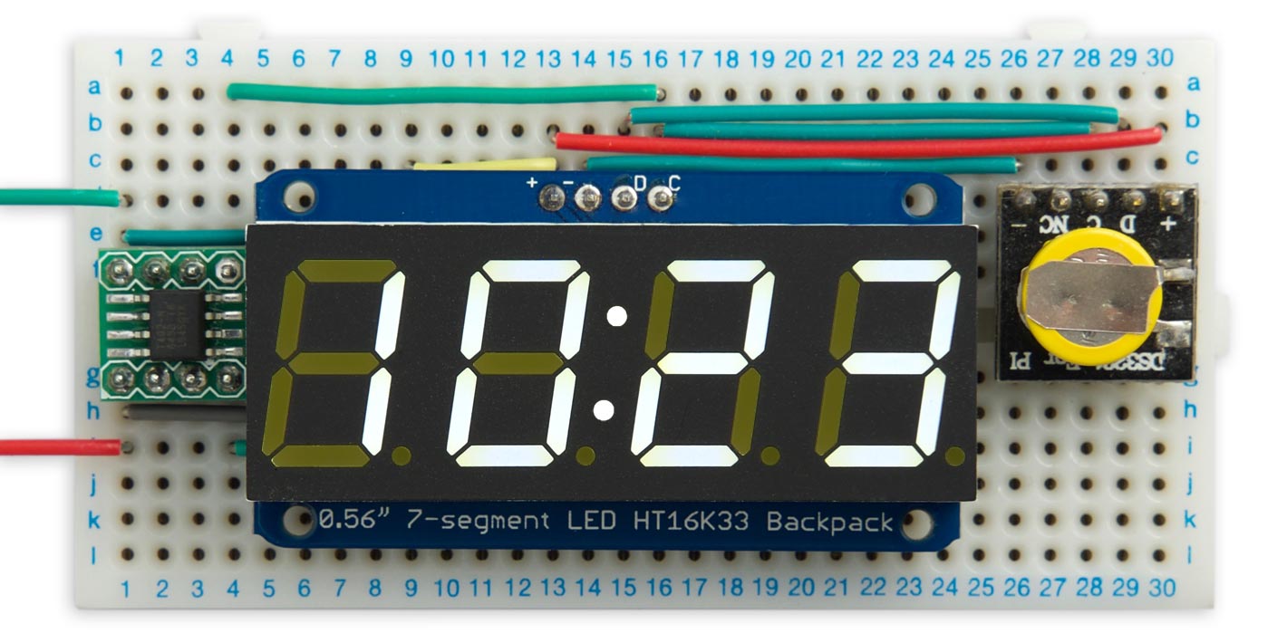
A simple I2C clock based on a 0-series ATtiny402 using these TinyMegaI2C routines.
The main difference between these routines and the standard Arduino Tiny Wire library is that these don't use buffers, so have minimal memory requirements, and don't impose a limit on transmissions.
Note that these routines are designed for the latest ATtiny 0-series and 1-series processors, and the 0-series ATmega chips; if you want minimal I2C routines for the earlier ATtiny processors, such as the ATtiny85, see my earlier article Minimal Tiny I2C Routines.
Introduction
Some time ago I wrote a set of minimal I2C routines for the older ATtiny processors, such as the ATtiny85. I recently needed a similar low-memory set of routines for the newer ATtiny 0-series and 1-series processors, and the 0-series ATmega chips such as the ATmega4809 as used in the latest Arduino boards, and so developed these routines. Fortunately one library can support all these devices because they have consistent peripherals, and the code is much simpler than my earlier TinyI2C library because the new chips include a TWI peripheral supporting the full I2C protocol.
I've named these routines TinyMegaI2C to distinguish them from my earlier library and from the existing Arduino Wire libraries, such as the one included in Spence Konde's megaTinyCore. Also, I wanted to emphasise that these routines don't follow the Arduino Wire library naming conventions.
These routines differ from the Arduino Wire library routines in the following ways:
Low memory requirements
These routines don't use buffers, reducing their RAM requirements to a couple of bytes. The standard 0-series ATmega Wire library uses 128-byte send and receive buffers, and the 0-series and 1-series ATtiny Wire libraries use 32-byte or 16-byte buffers, which on the smaller chips is a significant part of the available RAM. As far as I can see there's no need for buffering as the I2C protocol incorporates handshaking, using the ACK/NACK pulses.
Unlimited transmission length
These routines don't impose any limit on the length of transmissions. The standard Wire libraries limit the length of any transmission to the size of the buffer. This isn't a problem with many I2C applications, such as reading the temperature from a sensor, but it is a problem with applications such as driving an I2C OLED display, which requires you to send 1024 bytes to update the whole display.
Flexible read
These routines allow you to specify in advance how many bytes you want to read from an I2C peripheral, or you can leave this open-ended and mark the last byte read. This is an advantage when you don't know in advance how many bytes you are going to want to read.
Polling
For simplicity these routines use polling rather than interrupts, so they won't interfere with other processes using interrupts.
Compatibility
The beauty of the latest ATtiny 0-series, ATtiny 1-series, and ATmega 0-series ranges from Microchip is that they use the same peripherals, so these routines should work on any microcontroller in the range.
Performance
I've tested these routines on a selection of platforms, and the following table compares the total program memory (flash) and dynamic memory (RAM) usage of the TinyMegaI2C and Arduino Wire versions of the digital clock application, as reported by the Arduino IDE:
| Platform | TinyMegaI2C | Arduino Wire | ||
| Program memory | Dynamic memory | Program memory | Dynamic memory | |
| ATtiny402 | 1438 | 26 | 3380 | 107 |
| ATtiny3206 | 1686 | 26 | 3668 | 139 |
| Arduino Nano Every | 1768 | 26 | 3756 | 331 |
| Arduino Uni WiFi Rev 2 | 2112 | 26 | 4012 | 331 |
For the ATtiny402 and ATtiny3206 I used Spence Konde's megaTinyCore core [1].
For the Ardino Nano Every and Arduino Uno WiFi Rev 2 I used the Arduino megaAVR Boards core.
Here are the source files for the two versions of the I2C Clock:
- Using my TinyMegaI2C routines: I2C Digital Clock using TinyMegaI2C.
- Using the standard Arduino Wire library: I2C Digital Clock using Arduino Wire.
Description
Here's a description of the minimal TinyMegaI2C routines:
TinyMegaI2C.start(address, type)
Starts a transaction with the slave device with the specified address, and specifies if the transaction is going to be a read or a write. It returns true if the start was successful or false if there was an error.
The type parameter can have the following values:
- 0: Write to the device.
- 1 to 32767: Read from the device. The number specifies how many bytes you are going to read.
- -1: Read an unspecified number of bytes from the device.
If type is specified as -1 you must identify the last read by calling TinyMegaI2C.readlast() rather than TinyMegaI2C.read().
TinyMegaI2C.write(data)
Writes a byte of data to a slave device. It returns true if the write was successful or false if there was an error.
TinyMegaI2C.read()
Returns the result of reading from a slave device.
TinyMegaI2C.readLast()
Returns the result of reading from a slave device and tells the slave to stop sending. You only need to use TinyI2C.readlast() if you called TinyI2C.start() or TinyI2C.restart() with type set to -1.
TinyMegaI2C.restart(address, type);
Does a restart. The type parameter is the same as for TinyMegaI2C.start().
TinyMegaI2C.stop()
Ends the transaction; there's no return value.
Examples
To use the routines install the TinyMegaI2C library and include this at the top of your program:
#include <TinyMegaI2CMaster.h>
Port scanner
These routines let you write a simple port scanner to print out the addresses of any I2C devices found on the bus:
void setup() {
  TinyMegaI2C.init();
  Serial.begin(9600);
}

void loop () {
  delay(1000);
  Serial.println("Scanning...");
  for (int p=0; p<128; p++) {
    if (TinyMegaI2C.start(p, 0)) Serial.println(p);
  }
}
It uses the fact that TinyMegaI2C.start() returns false if no device was found with the corresponding address. For example, with the I2C clock circuit it prints out:
Scanning...
104
112
Writing to a slave
Writing to a slave is straightforward: for example, to write one byte:
TinyMegaI2C.start(Address, 0);
TinyMegaI2C.write(byte);
TinyMegaI2C.stop();
Reading from a slave
The TinyMegaI2C routines allow you to identify the last byte read from a slave in either of two ways:
You can specify the total number of bytes you are going to read, as the second parameter of TinyMegaI2C.start(). With this approach TinyMegaI2C.read() will automatically terminate the last call with a NAK:
TinyMegaI2C.start(Address, 2);
int mins = TinyMegaI2C.read();
int hrs = TinyMegaI2C.read();
TinyMegaI2C.stop();
Alternatively you can just specify the second parameter of TinyMegaI2C.start() as -1, and explicitly identify the last TinyMegaI2C.read command by calling TinyMegaI2C.readlast():
TinyMegaI2C.start(Address, -1);
int mins = TinyMegaI2C.read();
int hrs = TinyMegaI2C.readLast();
TinyMegaI2C.stop();
Writing and reading
Many I2C devices require you to write one or more bytes before reading, to specify the register you want to read from; the read should be introduced with an TinyMegaI2C.restart() call; for example:
TinyMegaI2C.start(Address, 0);
TinyMegaI2C.write(1);
TinyMegaI2C.restart(Address, 2);
int mins = TinyMegaI2C.read();
int hrs = TinyMegaI2C.read();
TinyMegaI2C.stop();
Get the TinyMegaI2C Library from GitHub here: TinyMegaI2C Library.
I2C clock example
Here's an example I used to test these routines; a simple digital clock based on the new 0-series 8-pin ATtiny402 using an I2C RTC module and an I2C 7-segment display.
The timekeeping is provided by an DS3231 RTC module [2], which is a low-cost, extremely accurate I2C real-time clock with an integrated temperature-compensated crystal oscillator. It also provides the date and two time of day alarms, although those features are not used in this application. Boards are available from several suppliers; I used one designed for the Raspberry Pi from Seeed Studio [3], available from The Pi Hut in the UK [4] and replaced the socket header with a plug header to make it easier to plug into a breadboard. A similar board is available from Adafruit [5].
For the display I used an I2C 7-segment display from Adafruit [6], available from Pimoroni in the UK [7]. It's available in a range of colours.
The program runs on an ATtiny402, but should work equally well on any of the new 0-series or 1-series ATtiny microcontrollers, or the 0-series ATmega microcontrollers. The ATtiny402 is only available in an SOIC package so I mounted it on a compact breakout board from HobbyTronics in the UK [8], but similar boards are available from Adafruit [9] and AliExpress [10].
The circuit
Circuit of the simple I2C clock based on a 0-series ATtiny402.
The modules each connect to the ATtiny402 using four wires: Data to PA1/SDA (pin 4), Clock to PA2/SCL (pin 5), +5V to VCC (pin 1), and Gnd to GND (pin 8). I used the default I2C address for each device; 0x70 for the RTC, and 0x68 for the display.
For information about uploading the program to the ATtiny402 see Getting Started with the New ATtiny Chips.
Setting the time
The following SetClock() routine sets the time:
void SetClock (int hr, int min) {
  TinyMegaI2C.start(RTCAddress, 0);
  TinyMegaI2C.write(0);
  TinyMegaI2C.write(0);
  TinyMegaI2C.write(min);
  TinyMegaI2C.write(hr);
  TinyMegaI2C.stop();
}
The first call to TinyMegaI2C.write() sets the starting register to write to in the DS3231; in this case 0, the seconds register. We then set the seconds to 0, the minutes to min, and the hours to hr. The times are defined in binary-coded decimal, so to set the time to 10:23 you need to call:
SetClock(0x10, 0x23);
Once you have set the time the backup battery will keep the time correct in the DS3231, so you should comment out this line and upload the program again. From now on the time will always be correct, even if you interrupt power to the circuit.
The clock program
First we define the seven-segment display patterns for the digits 0 to 9:
char Segment[10] = {0x3F, 0x06, 0x5B, 0x4F, 0x66, 0x6D, 0x7D, 0x07, 0x7F, 0x6F};
Next the routine InitDisplay() initialises the display and sets the brightness to 1:
void InitDisplay () {
  TinyMegaI2C.start(DisplayAddress, 0);
  TinyMegaI2C.write(0x21);
  TinyMegaI2C.restart(DisplayAddress, 0);
  TinyMegaI2C.write(0x81);
  TinyMegaI2C.restart(DisplayAddress, 0);
  TinyMegaI2C.write(0xe1);
  TinyMegaI2C.stop();
}
The last TinyMegaI2C.write() call sets the brightness, which can be from 0xe0 (off) to 0xef (maximum).
For each display digit you have to write two bytes to the display; this is for compatibility with Adafruit's other displays, and for this display the second byte is always zero:
void WriteWord (uint8_t b) {
  TinyMegaI2C.write(b);
  TinyMegaI2C.write(0);
}
Then here's the routine to write the time:
void WriteTime (uint8_t hrs, uint8_t mins) {
  TinyMegaI2C.start(DisplayAddress, 0);
  TinyMegaI2C.write(0);
  WriteWord(Segment[hrs / 16]);
  WriteWord(Segment[hrs % 16]);
  WriteWord(Colon);
  WriteWord(Segment[mins / 16]);
  WriteWord(Segment[mins % 16]);
  TinyMegaI2C.stop();
}
Curiously, the display is treated as having five digits, with the colon counted as the third digit, and to light it you have to write the value 2.
Finally, here's the main clock program:
void loop () {
 // Read the time from the RTC
  TinyMegaI2C.start(RTCAddress, 0);
  TinyMegaI2C.write(1);
  TinyMegaI2C.restart(RTCAddress, 2);
  int mins = TinyMegaI2C.read();
  int hrs = TinyMegaI2C.read();
  TinyMegaI2C.stop();

  // Write the time to the display
  WriteTime(hrs, mins);

  // Flash the colon
  Colon = 2 - Colon;
  delay(1000);
}
Uploading the program
Download the TinyMegaI2C library from GitHub and copy it to your Arduino libraries folder. Then upload the I2C Digital Clock program to the ATtiny402 is as follows:
- Make a UPDI programmer by installing ElTangas's jtag2updi program on an Arduino Uno, or other ATmega328P-based board, as described in Make UPDI Programmer.
- Install Spence Konde's megaTinyCore in the Arduino IDE, as described in megaTinyCore Installation.
- In the Arduino IDE select ATtiny412/402/212/202 from the megaTinyCore section of the Boards menu, and ATtiny402 from the Chip menu.
- Select jtag2updi (megaTinyCore) from the Programmer menu.
- Connect the Arduino Uno (or equivalent) to the chip you're programming, select its USB port from the Port menu, and select Upload.
You can ignore the error "Cannot locate flash and boot memories in description".
Here's the TinyMegaI2C library on GitHub: TinyMegaI2C Library.
and here's the I2C digital clock example: I2C Digital Clock using TinyMegaI2C.
- ^ megaTinyCore on GitHub.
- ^ DS3231 Datasheet on Maxim Integrated.
- ^ Mini RTC Module on Seeed Studio.
- ^ Mini RTC Module for Raspberry Pi on The Pi Hut.
- ^ DS3231 Precision RTC Breakout on Adafruit.
- ^ Adafruit 0.56" 4-Digit 7-Segment Display w/I2C Backpack on Adafruit.
- ^ Adafruit 0.56" 4-Digit 7-Segment Display w/I2C Backpack on Pimoroni.
- ^ SOIC to DIP Adapter 8-Pin on HobbyTronics.
- ^ SMT Breakout PCB for SOIC-8 on Adafruit
- ^ SOIC8 to DIP8 Adapter Board on AliExpress.
blog comments powered by Disqus