I2C GPS Module
27th September 2018
This project describes a simple GPS module which you can interface to via I2C. It uses an ATtiny841:
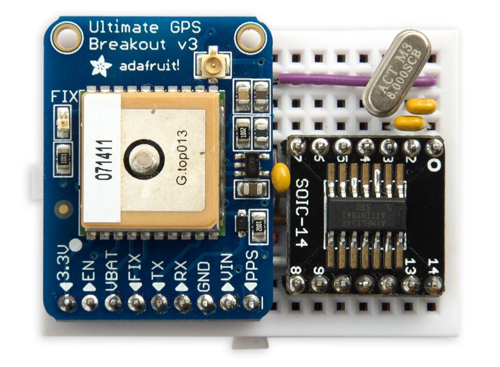
GPS module with an I2C interface, provided by an ATtiny841.
Introduction
Incorporating GPS into a project is quite daunting. First you have to parse the NMEA sentences from the GPS module you're using, and then if you're doing any calculations with the received longitudes and latitudes, you need to incorporate a floating-point GPS library with routines to perform the calculations.
If you need to do any other significant processing there's a chance that the GPS handling may interfere with your other tasks. Providing the GPS processing as a separate I2C module solves this problem.
I originally designed this to provide GPS support to boards running my Lisp interpreter, uLisp, but it could be useful for any other application where you want GPS data accessible via a simple I2C interface. It is based on my earlier project Making Your Own I2C Peripherals which described how to make an I2C slave device based on an ATtiny841.
GPS variables
The 18 bytes in the I2C data contain the raw GPS data extracted from the NMEA message:

These variables are as follows:
| Offset | Variable | Description |
| 0 | Time | The time in HH:MM format. |
| 2 | Csecs | The seconds in centiseconds. |
| 4 | Lat | The latitude in units of 1e-4 arc minutes. |
| 8 | Long | The longitude in units of 1e-4 arc minutes. |
| 12 | Knots | The speed, in 1e-2 knots. |
| 14 | Course | The course or track, in 1e-2 degrees. |
| 16 | Date | The date in DD:MM format. |
The angular measures, latitude and longitude, are returned in units of 1e-4 arc minutes. Thus one degree is represented as 600,000 units. This is designed to allow the arithmetic to be done using long integers, and is ideal for parsing the values returned by the GPS module without any loss of accuracy.
- If you prefer to work with the latitude and longitude in millionths of a degree, like some other GPS libraries, simply multiply by 5/3.
- If you want to work with the latitude and longitude as floating-point numbers, in degrees, divide them by 6e5.
- If you want to work with the latitude and longitude as degrees, arc minutes, and arc seconds use the calculations in the demo program below.
The circuit
I decided to base the circuit on an ATtiny841 because it provides a USART, and slave I2C capability in hardware:
Circuit of the I2C GPS module, based on an ATtiny841.
For convenience I used the Adafruit Ultimate GPS Breakout [1] available from Proto-PIC in the UK [2], but the circuit would work with other GPS modules; I reviewed a range of low-cost modules in my earlier article Flexible GPS Parser.
As the ATtiny841 is only available in a SOIC package I mounted it on a breakout board [3]. The GPS module and breakout board both fitted neatly on a mini breadboard, available from SparkFun [4] or HobbyTronics in the UK [5].
I used a crystal clock, although you could use the internal 8MHz oscillator provided you calibrate it with the OSCCAL register. I connected the 18pF capacitors between the crystal and Vcc, rather than GND as is conventional, to make the wiring easier on the prototyping board. This shouldn't affect the operation of the circuit.
Depending on what you're connecting the I2C GPS module to you may need 4.7kΩ pullup resistors between the SDA and SCL lines and Vcc. I found I didn't need them connecting the module to an Arduino Uno, but did need them with an Aduino Zero.
The program
First we define a typedef which defines a buffer_t type of 18 bytes which can alternatively be referred to by the GPS variable names or as a byte array:
// GPS variables
typedef union {
  struct {
    unsigned int Time, Csecs;
    long Lat, Long;
    unsigned int Knots, Course, Date;
  };
  uint8_t Data[buffersize];
} buffer_t;
The program works as follows. As each character is received from the GPS module it is parsed by the ParseGPS() routine, which writes the GPS variables into the gps.Data[] buffer until Fix indicates that a complete NMEA sentence has been received:
  do {
    while (!Serial.available());
    char c = Serial.read();
    ParseGPS(c);
  } while(!Fix);
The I2C interface generates a TWI interrupt, which calls the TWI_SLAVE interrupt for each byte written or read over the I2C interface. It's not safe for the I2C interface to read data directly from the gps.Data[] buffer. Imagine if the GPS data was being read from the GPS module when we access the buffer via I2S under interrupt. The two-byte time might be 11:59 when we read the LSB. However, it might have changed to 12:00 when we read the MSB. We would then end up with a time of 12:59, which would be totally incorrect. The same problem can occur for any of the other fields.
To prevent this we use two buffers. The GPS data is written to gps.Data[] by ParseGPS(), and when we have received a complete NMEA message this is copied to buf.Data[] in one operation, with interrupts disabled.
The same problem could potentially occur if we read directly from the buf.Data[] via I2C. The data could get updated between reading two successive bytes. The solution is to copy buf.Data[] to a third buffer, i2c.Data[], at the start of the I2C routine. We then read the data from this safe in the knowledge that it's consistent.
An alternative solution would be to make one process wait until the other one has completed. However, using separate buffers is a more elegant solution, ensuring that the data is always consistent without holding up the program.
The circuit provides an optional INT output, which is taken low when a complete NMEA sentence has been received to indicate that new data's ready. The output is taken high again when the data has been read by I2C.
TWI interrupt service routine
I decided to implement the slave software myself, rather than use a library, with the aim of keeping the project as simple as possible. Here's the code to handle the I2C interface:
ISR(TWI_SLAVE_vect) {
  if (TWSSRA & 1<<TWASIF) {                // Address received
    if (TWSSRA & 1<<TWDIR) {               // Master read
      // Copy buf buffer to i2c buffer so it's ready to be read
      for (int i=0; i<buffersize; i++) i2c.Data[i] = buf.Data[i];
      // Take INT pin high
      digitalWrite(Interrupt, HIGH);
      TWSCRB = 3<<TWCMD0;                  // ACK
    } else {                               // Master write
      TWSCRB = 3<<TWCMD0;                  // ACK
    }
  } else if (TWSSRA & 1<<TWDIF) {          // Data interrupt
    if (TWSSRA & 1<<TWDIR) {               // Master read
      if (Position >= 0 && Position < buffersize) {
        TWSD = i2c.Data[Position++];
        TWSCRB = 3<<TWCMD0;
      } else {
        TWSCRB = 2<<TWCMD0;                // NAK and complete
      }
    } else {                               // Master write
      Position = TWSD;                     // Write sets position
      TWSCRB = 3<<TWCMD0;                  // ACK
    }
  }
}
The logic of this routine is as follows:
- If the interrupt was for the address:
- If it is a read: make a copy of GPS data to be read by i2c, and ACK.
- If it is a write just ACK.
- If the interrupt was for data:
- If it is a read: read the data from the buffer at Position.
- If it is a write: set the buffer pointer, Position, to the byte.
Every I2C session starts with a write, to specify the offset in the buffer to read subsequent variables. You can then read an arbitrary number of bytes to get the variables you want to access.
Compiling the program
I compiled the program using Spence Konde's new ATTiny Core, which now supports all the ATtiny processors and supercedes the various earlier ATtiny cores [6]. Select the ATtinyx41 option under the ATtiny Universal heading on the Boards menu. Then choose B.O.D. Disabled, ATtiny841, 8 MHz (external) from the subsequent menus.
Connect the circuit to your computer via a suitable programmer, such as the Tiny AVR Programmer Board; see ATtiny-Based Beginner's Kit, then choose the programmer from the Programmer menu. Note that you must select a programmer marked (ATtiny) to upload properly to most supported chips - this is apparently due to a limitation in the IDE.
Choose Burn Bootloader to set the fuses appropriately. Then choose Upload to upload the program to the ATtiny841.
Here's the whole I2C GPS Module program: I2C GPS Module Program.
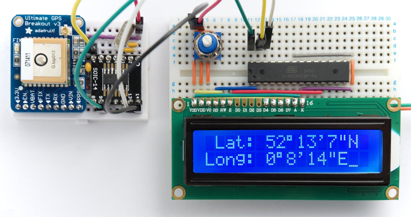
Testing the I2C GPS module with an LCD character display
To test the module I wrote a simple program to display the latitude and longitude on an LCD character display, using the circuit from my earlier project Simple LCD Character Display:
Here's the routine to read the long integer value returned by the I2C GPS module and print it as degrees, minutes, and seconds:
void printDMS (long ang) {
  int degs, mins, secs;
  degs = abs(ang)/600000; mins = (abs(ang) - degs*600000)/10000;
  secs = (abs(ang) - (long)degs*600000 - (long)mins*10000)*6/1000;
  lcd.print(degs); lcd.print((char)0xdf); lcd.print(mins);
  lcd.print('\''); lcd.print(secs); lcd.print('"');
}
I was pleased to discover that the LCD character display can display a degrees symbol; it's character 0xdf.
Finally, here's the routine to get the latitude and longitude from the I2C GPS module and write them to the LCD display:
void loop() {
  Wire.beginTransmission(0x3A);
  Wire.write(4);                                 // Start with latitude
  Wire.endTransmission();
  Wire.requestFrom(0x3A, 8);                     // Ask for 8 bytes
  long Lat = 0, Long = 0;
  for (int i=0; i<4; i++) Lat = Lat | (long)Wire.read()<<(i*8);
  for (int i=0; i<4; i++) Long = Long | (long)Wire.read()<<(i*8);
  lcd.cmd(0x01);
  lcd.print(" Lat: "); printDMS(Lat); lcd.print((Lat < 0) ? 'S' : 'N');
  lcd.cmd(0xc0);                                 // Clear
  lcd.print("Long: "); printDMS(Long); lcd.print((Long < 0) ? 'W' : 'E');
  while (digitalRead(Ready));                    // Wait for Ready to go low
}
Here's the whole I2C GPS Module Demo program: I2C GPS Module Demo Program.
Testing the I2C GPS module with uLisp
I also tested the I2C display module using my uLisp interpreter running on an Arduino Zero. Here's the uLisp program to read and print out the seven GPS values:
(defun read2 (str)
  (+ (read-byte str) (ash (read-byte str) 8)))

(defun read4 (str)
  (+ (read-byte str) (ash (read-byte str) 8)
     (ash (read-byte str) 16) (ash (read-byte str) 24)))

(defun rd ()
  (with-i2c (str 58)
    (write-byte 0 str)
    (restart-i2c str 18)
    (princ "Time:") (princ (read2 str))
    (princ ", Sec:") (princ (/ (read2 str) 100))
    (princ ", Lat:") (princ (/ (read4 str) 6e5))
    (princ ", Long:") (princ (/ (read4 str) 6e5))
    (princ ", Knot:") (princ (/ (read2 str) 100))
    (princ ", Course:") (princ (/ (read2 str) 100))
    (princ ", Date:") (princ (read2 str)) (terpri)))

(defun go ()
  (loop (rd) (delay 1000)))
Typing (go) prints out a line of the values every second; for example:
Time:1043, Sec:48, Lat:52.2187, Long:0.137323, Knot:0.09, Course:332.24, Date:2709
- ^ Ultimate GPS Breakout on Adafruit.
- ^ Ultimate GPS Breakout on Proto-PIC.
- ^ SMT Breakout PCB for SOIC-14 or TSSOP-14 on Adafruit.
- ^ Breadboard - Mini Modular on SparkFun.
- ^ Mini Breadboard from HobbyTronics.
- ^ ATTinyCore on GitHub.
blog comments powered by Disqus