Power Deliverer
23rd August 2022
This board allows you to use a USB-C power adapter as a power supply with a range of fixed voltages. It displays a list of the voltages and currents available from the adapter and allows you to select one:
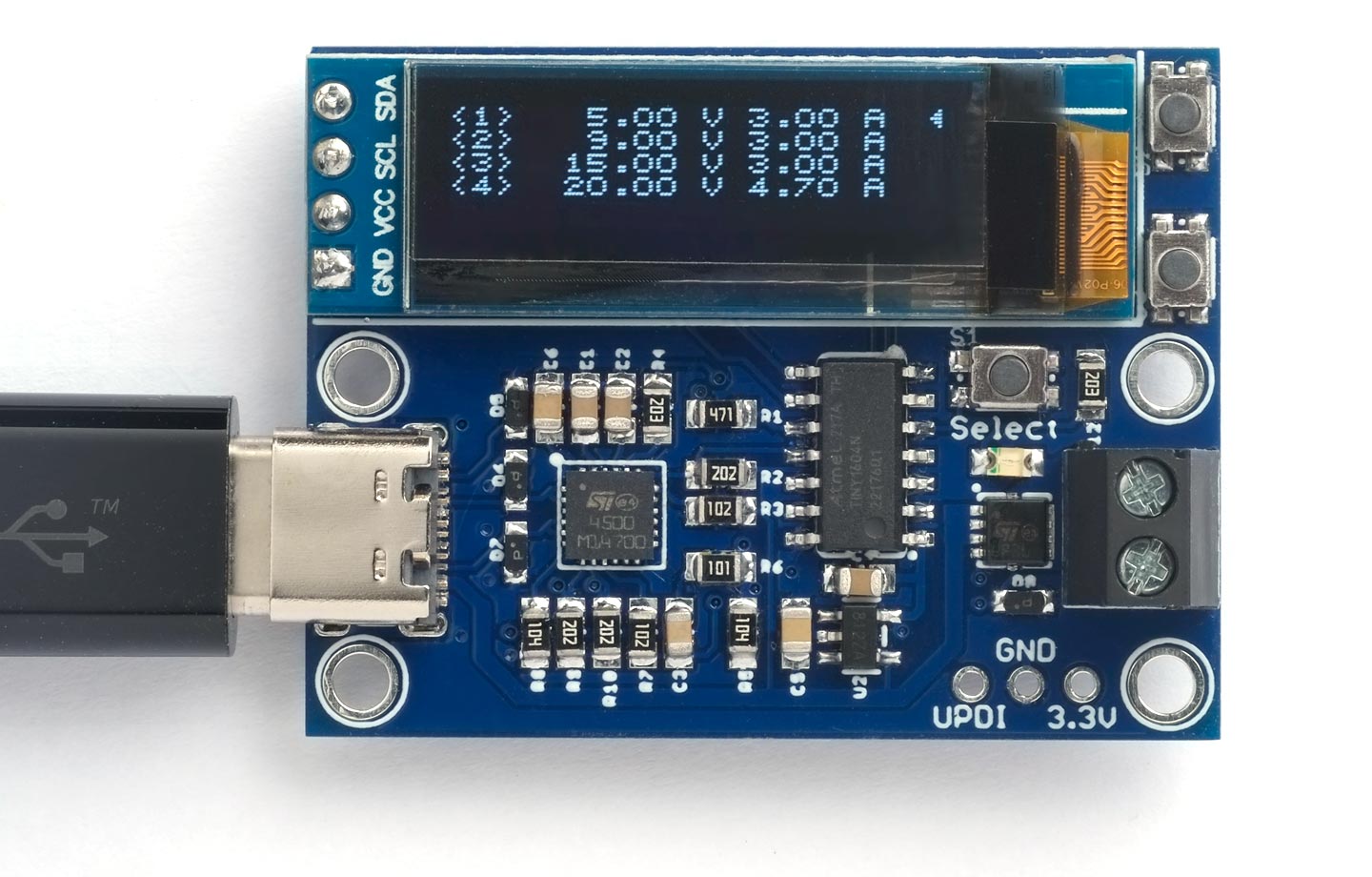
The Power Deliverer board, based on an STUSB4500 and an ATtiny1604 microcontroller,
showing the power profiles available from an Apple power adapter.
It's based on an STUSB4500 integrated circuit and an ATtiny1604 microcontroller, and it displays the information on a 128x32 OLED display.
Note that there is an improved version of this project with a current monitor; see Power Deliverer with Current Monitor.
Introduction
The original USB specification defined VBUS as a fixed 5V supply. USB-C extends this with a feature called Power Delivery. This allows a device to negotiate one of a number of fixed voltages from a USB-C Power Adapter: typically 5V, 9V, 12V, 15V, or 20V, at a current of up to 5A. It makes environmental sense, because a single USB-C power adapter can replace a multitude of different chargers for your various electrical devices.
I therefore set out to design a simple circuit that would allow you to use a USB-C power adapter as a convenient switched voltage lab power supply to power a variety of projects. It should display the voltage and current options available, and allow you to select one.
How it works
When you connect my Power Deliverer board to a USB-C charger with Power Delivery it displays a menu of the available voltages and their current capabilities, up to a maximum of 20V at 5A:

The power profiles from the AUKEY Omnia Mix 3 90W charger.
Each voltage/current option is referred to as a power profile. You can highlight one with the cursor, and then pressing the Select button will select this voltage on the output terminals, and the display shows the currently selected power profile:

Outputting a selected power profile.
A green LED also lights up to show that the output is active.
If the charger doesn't support Power Delivery the display shows:

Display if Power Delivery isn't supported.
Powering a project
Here's an example of the Power Deliverer powering a Peltier cooling device with 9V 3A from a USB-C power adapter:
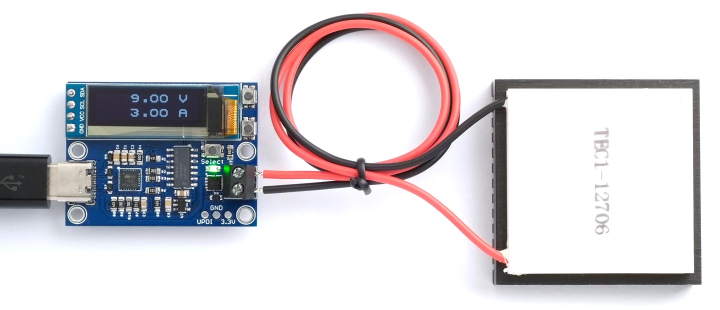
The Power Deliverer board powering a Peltier cooling device with 9V 3A from a USB-C power adapter.
IMPORTANT: This project is only intended for hobby use, and is not an end-user product. I haven't tested it to make sure that it meets any regulatory requirements, including interference and safety, and it's possible that a programming fault could potentially cause it to output a higher voltage than selected. Please do not use it to power expensive equipment!
USB-C power adapters
Several manufacturers now supply USB-C power adapters that support Power Delivery. For example, here's a list of the different USB-C power adapters that Apple have produced, and the power profiles they provide:
| Max. Power | Model | Voltages |
| 18W * | A1695 | 9V 2A, 5V 3A. |
| 20W | A2244 | 9V 2.22A, 5V 3A. |
| 29W * | A1540 | 14.5V 2A, 5V 2.4A. |
| 30W | A2164 | 20V 1.5A, 15V 2A, 9V 3A, 5V 3A. |
| 35W dual † | A2579 | 20V 1.75A, 15V 2.33A, 9V 3A, 5V 3A. |
| 35W dual | A2676 | 20V 1.75A, 15V 2.33A, 9V 3A, 5V 3A. |
| 61W * | A1718 | 20.3V 3A, 9V 3A, 5V 2.4A. |
| 61W | A1947 | 20.3V 3A, 15V 3A, 9V 3A, 5V 3A. |
| 67W | A2518 | 20.3V 3.3A, 15V 5A, 9V 3A, 5.2V 3A. |
| 87W * | A1719 | 20.2V 4.3A, 9V 3A, 5.2V 4.2A. |
| 96W | A2166 | 20.5V 4.7A, 15V 3A, 9V 3A, 5.2V 3A. |
| 140W | A2452 | 28V 5A, 20.5V 5A, 15V 5A, 9V 3A, 5.2V 3A. |
* Discontinued.
† Compact with folding prongs. All the others have removable prongs.
If you've got an Apple Power Adapter you can check the power profiles available on the label on the side of the adapter. For example, here's the 35W dual power adapter A2676:
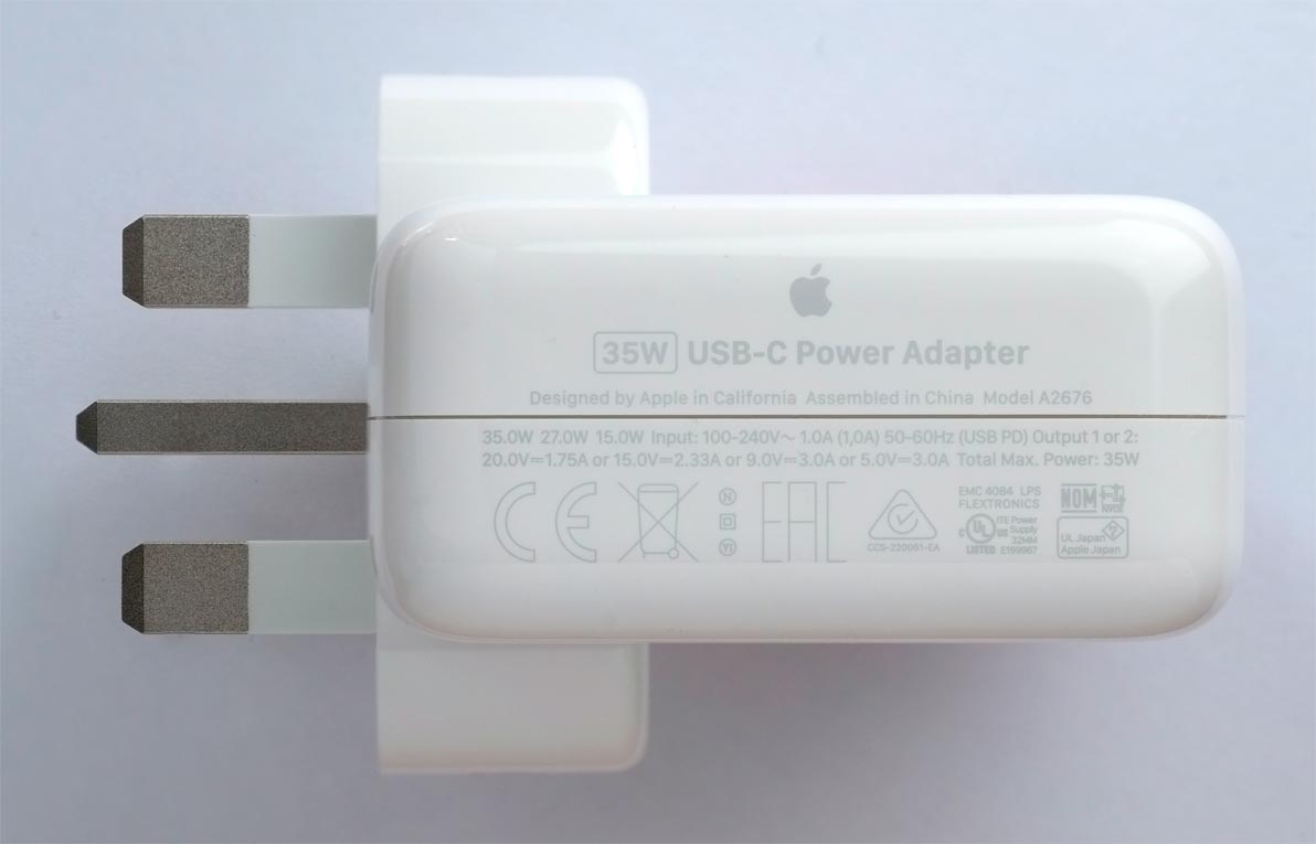
The Apple 35W dual power adapter.
Note that there are often minor differences between what's written on the label, and the power profiles the power adapter actually returns.
Interface chips
I investigated three alternative USB-C interface chips that support USB-C Power Delivery:
Infineon CYPD3177
The CYPD3177 from Infineon (formerly Cypress) [1] allows you to set the Power Delivery parameters using four resistor dividers: minimum voltage, maximum voltage, coarse current, and fine current. It also offers I2C control, but that's not documented in the main datasheet. There's a reasonably priced evaluation board, the CY4533 [2].
ON Semiconductor FUSB302B
The ON Semiconductor FUSB302B [3] provides an I2C interface, but the interface protocol works at quite a low level, so I anticipated that it would require a lot of programming to implement what I wanted. For an example of a Power Delivery project based on it see Jason Cerundolo's USB-C Explorer on GitHub [4].
STMicroelectronics STUSB4500
The chip I finally chose was the STUSB4500 from STMicroelectronics [5]. It gives you control over the Power Delivery options via an I2C interface, although you can get some basic functionality without that. Note: Don't confuse this with the STUSB4500L, which only supports 5V output.
Approach
My aim was to make the circuit and program as simple as possible, while meeting my target specification. For ways in which it could be extended see Further suggestions below.
To design this project I relied on the following resources:
For the circuit I studied the application in the STUSB4500 datasheet [6] and the circuit of the STUSB4500 Evaluation Board [7]. I also looked at two other open-source projects based on the STUSB4500: Mike Rankin's ESP32 USB-C Power Supply [8], and the SparkFun Power Delivery Board [9]. The circuits are all similar, and tend to follow the datasheet application in using STMicroelectronics components for the MOSFET and transient voltage suppressors; I discuss some alternatives below.
For the programming side the STUSB4500 datasheet isn't very useful, as it doesn't include much information about the I2C interface. I referred to the STUSB4500 Software Programming Guide [10], ardnew's Arduino library for the STUSB4500 [11], and the STMicroelectronics STUSB4500 SW drivers and tools repository [12].
Terminology
First some notes about terminology. The USB-C charger is referred to as the Power Delivery Source, or PD Source. The Power Deliverer board is a PD Sink; it receives power from the PD Source.
The definition of each voltage/current power profile is referred to as a PDO (Power Data Object).
STUSB4500 operation
The way the STUSB4500 works is that it allows you to define between one and three Sink PDOs, and it automatically selects the highest-voltage Source PDO available from the charger with the required current capability. Initially three default Sink PDOs are defined:
- 5V 1.5A
- 15V 1.5A
- 20V 1A
You can't redefine the first option, 5V 1.5A, and this will always match if the other two options are not available.
Compatibility
I've tested the Power Deliverer with Apple's 35W dual power adapter (A2676) [13], Apple's 96W power adapter (A2166) [14], Apple's 140W power adapter (A2452) [15], a UGREEN 20W PD Fast Charger with PPS (CD137) [16], and an AUKEY Omnia Mix 3 90W charger (PA-B6S) [17].
USB-C Power Delivery 3.1
The STUSB4500 is compatible with USB-C Power Delivery 2.0, which supports power profiles up to 20V at 5A, or 100W. An extension to the standard, called USB Power Delivery 3.1, extends this range up to a maximum of 48V at 5A, or 240W. For example, Apple's 140W power adapter uses the new standard to offer 28V at 5A. The Power Deliverer doesn't show power profiles above 20V, or PPS profiles.
The circuit
Here's the circuit of the Power Deliverer:
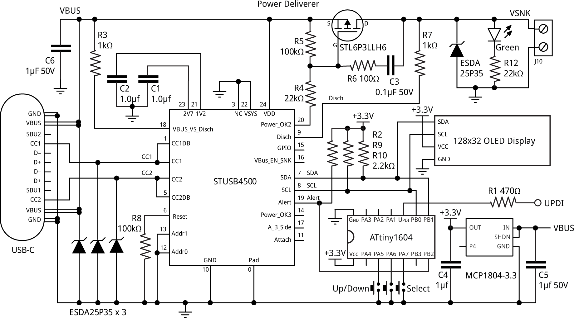
The circuit of the Power Deliverer board, based on an STUSB4500 and an ATtiny1604 microcontroller.
Unfortunately the STUSB4500 seems to be out of stock from all suppliers at the moment, but hopefully they will be back in stock at some point. Alternatively you can do what I did, and unsolder one from an EVAL-SCS001V1 evaluation board; these still seem to be available from several suppliers.
The STUSB4500 is controlled via the I2C interface by an ATtiny1604 processor. You could probably also use an ATtiny1614 or ATtiny1624 without any changes, but I haven't tried them.
For the display I used a low-cost 128x32 monochrome OLED display based on the SSD1306 display controller [18]. To make it possible to fit five PDOs on the display I designed a 5x5 pixel font, allowing a display of 5 lines of 21 characters.
The microcontroller and display circuitry has to be powered from whatever voltage you have selected from the PD Source. This could potentially be 20V, so a regulator is needed to drop this to 3.3V. The usual APA2112K-3.3 or MIC5225-3.3 won't be suitable as these have maximum voltage inputs of 6V or 16V respectively. I chose an MCP1804-33 [19] which allows an input of up to 28V. The final power consumption of the circuit was about 10mA, so the regulator will only have to dissipate about 0.16W.
The output is switched by a P-MOSFET. This needs to handle the highest possible PDO of 20V at 5A. I tested two alternatives with compatible footprints: the ST Microelectronics STL6P3LLH6 [20], with a rating of 30V, 6A and a typical on-resistance of 24mΩ, and the Vishay SI7619DN [21] with a rating of 30V, 24A, and 34mΩ. The on-resistance is important because it determines the dissipation at maximum load.
The circuit is protected from voltage spikes on the USB-C input, and the output terminals, by four ESDA25P35 transient voltage suppression (TVS) diodes [22]. The one specified has a breakdown voltage of 25V and can handle 35A, and other 0603 TVS diodes with the same rating should be suitable.
All the resistors and capacitors are 0805 size. Because the VBUS line can be up to 20V, several components need to be rated to handle at least 20V. I've therefore specified that C5 and C6 should be 1µF 50V, and C3 should be 0.1µF 50V.
All the other application circuits I looked at control the output MOSFET from the STUSB4500 signal VBUS_EN_SNK, which enables the output when any Sink PDO matches the Source PDOs. Since the default 5V 1.5A Sink PDO will always match, this makes it impossible to switch off the output. In this circuit I therefore connected the gate to the POWER_OK2 signal instead, which makes it possible to disable the output by setting the number of Sink PDOs to 1.
► Parts list
Construction
I designed a PCB in Eagle and sent it to PCBWay [23] for production. There's a link at the end of the article if you want to make yourself a board.
I used a Youyue 858D+ hot air gun at 275°C and Chip Quik SMD291AX10T3 solder paste to solder the components, but you could also use a reflow oven. The STUSB4500 is in a QFN-24 package, and I don't think you'll be able to solder this with a soldering iron.
Make sure that the four lugs on the USB-C socket are well soldered to the matching holes on the PCB. Otherwise it's easy to accidentally yank off the socket when inserting or removing the USB-C connecter, as I did with one of my prototypes.
Solder the display in position last, using a soldering iron, as it will be damaged by a hot air gun or reflow oven. I attached it to the main board with a double-sided foam pad.
Testing the board
Even before you have connected the display or uploaded a program to the ATtiny1604, you can connect the board to a power adapter and the STUSB4500 should automatically select the highest default Sink PDO that the PD Source provides. In my case I was testing with the Apple 96W charger, so the 20V 1A profile was selected, and there was 20V on the VBUS line. Note that it won't actually appear on the output terminals because the output MOSFET won't be turned on.
If this isn't working the most likely explanation is that there is a bad connection to the USB-C connector, the STUSB4500, or one or more of the TVS diodes is the wrong way round (I initially had all of these problems!).
The program
When the USB cable is connected the STUSB4500 is reset, and the program connects to it via I2C. It first checks that the source supports power delivery; otherwise a message "NO PD" is displayed.
Then the program queries the PD Source to send a list of the power profiles it offers. There can be up to 7, but my program currently only reads the first five, as none of the chargers I investigated offered more than five profiles.
The program then displays a list of the available power profiles on the display, and you can press the Up/Down buttons to highlight the one you want to use.
Finally, pressing the Select button selects the highlighted profile, and displays its details on the display. The green LED also lights up to show that the output is active.
The way the program handles these steps is explained in greater detail in the following sections.
The display
To fit the five power profiles on the 32-pixel high display I designed a compact font based on a 5x5 matrix. It only provides the digits and a few additional characters. For the selected power profile the font is displayed double size, and I've used my smoothing routine, Smooth Big Text, to give smoothed characters.
The SSD1306 display controller doesn't support reading back from the display, so I wrote the display image into a RAM buffer:
// Buffer of 5 lines x 128 characters
uint8_t ScreenBuf[5][128];
I then used a routine UpdateScreen() to refresh the display from the buffer.
A separate routine PlotCursor() displays an arrow cursor at the right-hand edge of the display, for use when selecting a profile.
Initialising the STUSB4500
The STUSB4500 handles the communication with the PD Source, but your program has to decode the information returned from the PD Source.
The information received from the PD Source is made available in a series of status registers, with I2C addresses 0x0D to 0x16. See the STUSB4500 software programming guide for more details. A flag in the ALERT_STATUS register indicates whether each of these status registers has changed.
The InitSTUSB() routine initialises the STUSB4500 by reading each of the status registers, to clear the corresponding flag in the ALERT_STATUS register, and it then programs the ALERT_STATUS_MASK register to specify which registers should cause an interrupt on the Alert output:
void InitSTUSB () {
  // Read status registers to clear flags
  Wire.beginTransmission(STUSBAddress);
  Wire.write(PORT_STATUS);
  Wire.endTransmission();
  Wire.requestFrom(STUSBAddress, 0x16-0x0D+1);
  for (int i=0; i<0x16-0x0D+1; i++) Wire.read();

  // Only interested in PRT_STATUS_AL alert
  Wire.beginTransmission(STUSBAddress);
  Wire.write(ALERT_STATUS_MASK);
  Wire.write(~PRT_STATUS_AL);
  Wire.endTransmission();
}
The various status registers provide a lot of information available about the USB connection, orientation, etc, but for this project I was only interested in the protocol status register, PRT_STATUS, which specifies when the power profiles have been received from the PD Source. I therefore only enabled this alert in the ALERT_STATUS_MASK register.
An earlier version of my program used polling to wait until the PD Source had sent the power profiles, and it then read them from the RX_HEADER and RX_DATA_OBJ registers. However, you have to read these registers within about 3ms, as they are overwritten by the next message, so I decided it would be better to use an interrupt service routine to read them. The STUSB4500 Alert output is connected to the PB2 input on the ATtiny1604, and an interrupt is defined on the falling edge of this input:
void AlertEnable () {
  PORTB.PIN2CTRL = PORT_ISC_FALLING_gc;               // Pin change interrupt on PB2
}
Alert interrupt service routine
Here's the interrupt service routine:
ISR(PORTB_PORT_vect) {
  PORTB.INTFLAGS = PIN2_bm;                           // Clear interrupt flag
  uint8_t alertStatus = ReadRegister(ALERT_STATUS);

  if ((alertStatus & PRT_STATUS_AL) != 0) {
    uint8_t prtStatus = ReadRegister(PRT_STATUS);
    if ((prtStatus & MSG_RECEIVED) != 0) {
      // Read message header
      ReadHeader();
      if (PDHeader.messageType == SOURCE_CAPABILITIES) {
        Objects = PDHeader.objects;
        ReadObjects();
        GotPDs = true;
      }
    }
  }
}
It performs the following steps:
If the PRT_STATUS_AL flag is set in the ALERT_STATUS register (not strictly necessary, as it's the only alert that can cause an interrupt):
- Read the PRT_STATUS register.
- If the MSG_RECEIVED bit is set, it indicates that we've received a message.
- Read the message header RX_HEADER into the global variable PDHeader by calling ReadHeader().
- If the messageType field in the header is equal to SOURCE_CAPABILITIES it indicates that this is a source capabilities message containing the PDOs.
- Set Objects to the number of Source PDOs.
- Call ReadObjects() to read the first five PDOs from the RX_DATA_OBJ registers into the structure PDObject[5].
- Set the global variable GotPDOs to true to indicate that we have received the PDOs.
When we've got the power profiles we can disable the Alert interrupt, because we don't need any further information from the PD Source.
Reading the header
The ReadHeader() routine reads the 16-bit header into the global variable PDheader, which is defined as a PDHeader_t bit field:
void ReadHeader () {
  Wire.beginTransmission(STUSBAddress);
  Wire.write(RX_HEADER);
  Wire.endTransmission(false);
  Wire.requestFrom(STUSBAddress, 2);
  PDHeader.bytes[0] = Wire.read(); PDHeader.bytes[1] = Wire.read();
}
The most useful fields are PDHeader.messageType, which specifies the type of message, and PDHeader.objects, which gives the number of PDOs received.
Reading the power profiles
The ReadObjects() routine reads the PDOs into the global array PDObject[5], which is defined as a PDO_t bit field:
void ReadObjects () {
  Wire.beginTransmission(STUSBAddress);
  Wire.write(RX_DATA_OBJS);
  Wire.endTransmission(false);
  Wire.requestFrom(STUSBAddress, numObjects*4);
  for (int obj=0; obj<numObjects; obj++) {
    for (int i=0; i<4; i++) PDObject[obj].bytes[i] = Wire.read();
  }
}
Each PDO is four bytes. The most useful fields are PDObject.voltage, which specifies the voltage in units of 50mV, PDObject.current, which specifies the maximum current in units of 10mA, and PDObject.type, which is zero for a fixed PDO (not currently used).
Displaying the profiles
When the main program detects that GotPDOs is true we can call DisplayPDObjects() to display the power profiles in PDObject[] on the display:
void DisplayPDObjects () {
  for (int obj = 0; obj<Objects; obj++) {
    PlotChar(Bra, obj, 0);
    PlotChar(obj+1, obj, 1);
    PlotChar(Ket, obj, 2);
    PlotVal(PDObject[obj].voltage, obj, 5, true);
    PlotVal(PDObject[obj].current, obj, 13, false);
  }
}
We also display the cursor, and enable interrupts on the Up/Down buttons to allow them to be used to select one of the profiles.
Push buttons
The three push buttons are connected to inputs on port A with pullups and pin-change interrupts. I chose to put the buttons on a different port from the Alert signal so they would have a separate interrupt-service routine, which makes the programming easier. The button interrupt service routine simply sets the global flag SelectPressed, or increments or decrements the cursor position:
ISR(PORTA_PORT_vect) {
  uint8_t flags = PORTA.INTFLAGS;
  PORTA.INTFLAGS = 1<<Up | 1<<Down | 1<<Select;        // Clear interrupt flags
  if (flags & 1<<Select) { SelectPressed = true; return; }
  if (flags & 1<<Up) Cursor = (Cursor + Objects - 1) % Objects;
  if (flags & 1<<Down) Cursor = (Cursor + 1) % Objects;
  PlotCursor(Cursor);
}
Selecting a profile
Pressing the Select button selects the currently highlighted profile. This works as follows:
As explained above, the STUSB4500 provides three Sink PDOs, and will automatically activate the highest matching Source PDO. Profile 1 is always the default 5V 1.5A profile. To select another PDO we therefore set Sink PDO 2 to its characteristics, and update the PD Source.
The steps are:
- Call SelectPDO() to set Sink PDO 2 to the PDO currently highlighted by the cursor:
void SelectPDO (uint8_t object) {
  uint8_t index = 1;
  Wire.beginTransmission(STUSBAddress);
  Wire.write(DPM_SNK_PDOS + 4*index);
  for (int i=0; i<4; i++) Wire.write(PDObject[object].bytes[i]);
  Wire.endTransmission();
}
- Call UpdatePDONumber(2) to set the total number of Sink PDOs to 2:
void UpdatePDONumber (uint8_t Number_PDO) {
  if (Number_PDO >= 1 && Number_PDO <= 3) {
    Wire.beginTransmission(STUSBAddress);
    Wire.write(DPM_PDO_NUMB);
    Wire.write(Number_PDO);
    Wire.endTransmission();
  }
}
- Call SendSoftReset() to request the matching PDO from the PD Source.
The selected PDO will be sent to the output, and the green LED will light up to show that the output is active.
The main program
The main program simply alternates between displaying the profiles, or outputting the selected voltage, each time Select is pressed:
void loop() {
  DisplayProfiles();
  SelectVoltage();
}
Compiling the program
Compile the program using Spence Konde's megaTiny Core on GitHub. Choose the ATtiny3224/1624/1614/1604/824/814/804/424/414/404/241/204 option under the megaTinyCore heading on the Board menu. Check that the subsequent options are set as follows (ignore any other options):
Chip: "ATtiny1604" (or as appropriate)
Clock: "20 MHz internal"
Then upload the program to the Power Deliverer using a UPDI programmer. The recommended option is to use a USB to Serial board, such as the SparkFun FTDI Basic board [24], connected with a 4.7kΩ resistor as follows:
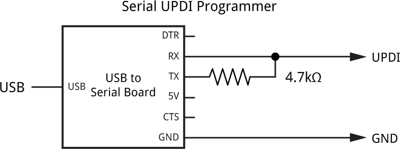
The simplest way to provide the 3.3V is to power the Power Deliverer from the USB port, and don't connect the 5V from the Serial UPDI Programmer. Set the Programmer option to "SerialUPDI with 4.7k resistor or diode (230400 baud)".
Resources
I've made two versions of the Power Deliverer program; one using Arduino Wire, and one using my more compact I2C library, TinyI2C (see TinyI2C on GitHub).
Here's the Arduino Wire version: Power Deliverer Wire Version.
And here's the TinyI2C Version: Power Deliverer TinyI2C Version.
Get the Eagle files for the PCB on GitHub here: https://github.com/technoblogy/power-deliverer.
Or order boards from OSH Park here: Power Deliverer.
Or order boards from PCBWay here: Power Deliverer.
Further suggestions
You could add a current sensor, to allow you to show an active display of the current being drawn by the load. You could either use an I2C sensor such as the INA219, or an analogue sensor such as the INA199 which you could read with an analogue input on the ATtiny1604.
Also, the USB-C Power Delivery protocol receives other information about the USB connection, which you could access and show on the display.
Update
11th November 2022: Made a minor correction to the parts list.
- ^ CYPD3177 datasheet on Infineon.
- ^ CY4533 Evaluation Board on Mouser.
- ^ FUSB302B Datasheet on Mouser.
- ^ USB-C Explorer on GitHub.
- ^ STUSB4500 datasheet on Mouser.
- ^ STUSB4500 Datasheet on Farnell.com.
- ^ EVAL-SCS001V1 Datasheet on RS-Online.
- ^ ESP32 USB-C Power Supply on GitHub.
- ^ SparkFun Power Delivery Board - USB-C on SparkFun.
- ^ STUSB4500 Software Programming Guide on GitHub.
- ^ STUSB4500 Arduino Library on GitHub.
- ^ STUSB4500 SW drivers and tools on GitHub.
- ^ 35W Dual USB-C Port Power Adapter on Apple UK.
- ^ 96W USB-C Power Adapter on Apple UK.
- ^ 140W USB-C Power Adapter on Apple UK.
- ^ UGREEN USB-C Charger Plug 20W on Amazon.
- ^ Aukey PA-B6S Omnia 90W 3-Port Charger on MyMemory.
- ^ 128x32 I2C OLED display on AliExpress.
- ^ MCP1804-33 datasheet on Microchip.
- ^ STL6P3LLH6 datasheet on mouser.co.uk.
- ^ Si7619DN datasheet on mouser.co.uk.
- ^ ESDA25P35 datasheet on mouser.co.uk.
- ^ PCBWay PCB prototype service.
- ^ SparkFun FTDI Basic Breakout - 5V on Sparkfun.
blog comments powered by Disqus