Timescale Clock
8th November 2014
This Timescale Clock is an analogue clock with a difference – it displays the time on a horizontal scale. The scale scrolls slowly to the left, so you can see the time to within a minute by the position of a fixed pointer in the centre of the scale:
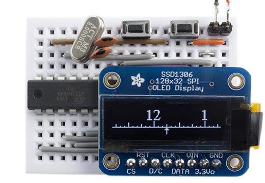
ATtiny84-based Timescale Clock. It's a quarter past 12.
The clock uses a small 128x32 monochrome OLED display, run by a crystal-controlled ATtiny84. Alternatively you could drive the clock using an Arduino.
Introduction
The idea for this clock was inspired by two observations:
- You don't need the minute hand to be able to tell the time on a traditional circular analogue clock.
- If there's no minute hand, you only need to see the part of the dial close to the hour hand.
This led to the design of this clock based on a small rectangular display, which shows just the relevant section of the clock face as a linear scale, a bit like the scale on some mechanical weighing machines.
OLED Display
For the clock I chose a 128x32 OLED display, a small display about 2.5cm (1") wide with a very clear, bright monochrome display, and an SPI interface, available from Adafruit [1].
Despite what some tutorials say, you don't need a RAM buffer to use this display because it has its own internal memory. The display is divided into four 8-pixel high bands, referred to as pages, and you can write a vertical column of 8 pixels at a time. It's easy to write bitmap characters to the display; you just specify the page and starting column, and then write the character definitions for successive characters. For example, you could use it for a character display of 4 lines x 21 characters with just an 84-byte buffer for the characters.
The display supports three different addressing modes; I use page addressing mode, which writes successive bytes starting from a given column in a given page. For example, here's the code that writes the pointer in the middle of the bottom page of the clock display:
void DisplayPointer() {
  Command(0xB0); // Page 0
  Command(0x0E); // Column low
  Command(0x13); // Column high
  Data(0b00100000);
  Data(0b01100000);
  Data(0b11111111);
  Data(0b01100000);
  Data(0b00100000);
}
The display driver supports I2C, 3-wire SPI, and 4-wire SPI interfaces. In the 3-wire SPI mode the display distinguishes between control commands and display data using a 9th serial bit; in the 4-wire SPI mode a separate D/C pin performs this function. For their SPI version of this display Adafruit unfortunately chose to hard-wire it in 4-wire SPI mode, which needs an extra pin. My first prototype used an ATtiny85, but I realised that there aren't quite enough pins left over to use an external crystal for the timing, so I changed the circuit to use an ATtiny84, which provides plenty of I/O lines. The ATtiny85 would be fine if you were using an external time source, such as the DS3234 [2].
Circuit
Here's the circuit:
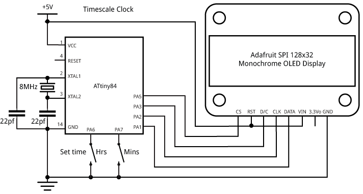
Timescale Clock circuit.
The clock includes two push-buttons to allow you to set the time. One steps through the hours every second, and the other steps through the minutes every second.
The clock can be powered from 3 to 5V, and takes about 8mA, so will run for about 5 days from a 1200mAH LIPO cell.
Program
The program sends data to the display using software SPI; here's the routine:
void Data(char d) {
  digitalWrite(cs, LOW);
  for(uint8_t bit = 0x80; bit; bit >>= 1) {
    digitalWrite(clk, LOW);
    if (d & bit) digitalWrite(data, HIGH);
    else digitalWrite(data, LOW);
    digitalWrite(clk, HIGH);
  }
  digitalWrite(cs, HIGH);
}
Commands are sent using the same routine, but having first taken the D/C line low:
void Command(char c) {
  digitalWrite(dc, LOW);
  Data(c);
  digitalWrite(dc, HIGH);
}
For time-critical applications you could get extra speed by using the ATtiny84 USI port to implement hardware SPI, but for this clock software SPI is simpler and fast enough.
The main loop of the program is run once a second; it updates the timescale, draws in the previous hour and next hour digits, and checks whether either of the time setting buttons is pressed:
void loop () {
  int x;
  unsigned long Start = millis();
  int Minute = (Time / 60) % 60;
  int Hour = (Time / 3600) % 12;
  // Write the time scale
  DisplayTimescale(Minute);
  // Previous hour
  x = 64 - Minute - 8;
  if (x > 0) DisplayDigit(x, Hour); else DisplayDigit(x0, Blank);
  x0 = x;
  // Next hour
  x = 124 - Minute - 8;
  if (x < 120) DisplayDigit(x, (Hour+1)%12); else DisplayDigit(x1, Blank);
  x1 = x;
  // Wait until the end of this second
  Start = Start + 1000;
  do ; while (millis() < Start);
  // Read set-time buttons
  if (!digitalRead(SetMin)) Time = ((Time / 60) + 1) * 60;
  else if (!digitalRead(SetHr)) Time = ((Time / 60) + 60) * 60;
  else Time = Time + 1;
}
Bitmaps
The digits for each hour, including "10", "11", and "12", are defined by 12 16x16 bitmaps in the array ClockDigits[]. This is stored in program memory using PROGMEM to avoid using up RAM. I created these in Photoshop, and then saved them in monochrome BMP format [3], which stores the raw data without any compression. I then dumped out the bytes using the Unix command:
xxd -i Bitmap.bmp
You could use this same technique to convert arbitrary bitmap images and display them. I can give more information about how to do this if anyone's interested.
Compiling the program
I compiled the program using the ATtiny core extension to the Arduino IDE [4]. This doesn't include a setting for the ATtiny84 with an 8MHz crystal, so I added the following definition to the boards.txt file:
###########################################################################

attiny84at8x.name=ATtiny84 @ 8 MHz  (external crystal; BOD disabled)

attiny84at8x.upload.using=arduino:arduinoisp
attiny84at8x.upload.maximum_size=8192

# Ext. Crystal Osc. 8.0 MHz; Start-up time: 16K CK/14 CK + 65 ms; [CKSEL=1111 SUT=11]
# Brown-out detection disabled; [BODLEVEL=111]
# Preserve EEPROM memory through the Chip Erase cycle; [EESAVE=0]

attiny84at8x.bootloader.low_fuses=0xFF
attiny84at8x.bootloader.high_fuses=0xD7
attiny84at8x.bootloader.extended_fuses=0xFF
attiny84at8x.bootloader.path=empty
attiny84at8x.bootloader.file=empty84at8.hex

attiny84at8x.build.mcu=attiny84
attiny84at8x.build.f_cpu=8000000L
attiny84at8x.build.core=tiny

###########################################################################
Here's the whole Timescale Clock program: Timescale Clock Program.
Addenda
After designing this clock I discovered that someone had already come up with a similar idea [5], although it uses a mechanical scale rather than a digital display. I'd be interested to hear of any other designs along the same lines.
26th May 2015: I've just discovered another rather wonderful mechanical timescale clock, using digits on a bicycle chain: http://www.iainclaridge.co.uk/blog/1692.
- ^ Monochrome 128x32 SPI OLED graphic display on Adafruit.
- ^ DeadOn RTC - DS3234 Breakout on Sparkfun.
- ^ BMP file format on Wikipedia.
- ^ ATtiny core for Arduino: arduino-tiny on Google Code.
- ^ Linear Clock by Euphy on Instructables.
blog comments powered by Disqus