One Input Keypad Interface
13th June 2014
This post shows how to interface a keypad of 12 or 16 buttons to a single analogue input. Pushbutton keypads provide a low-cost way to provide data entry to a project; they are available in 12-button or 16-button versions, and are available from most suppliers like Sparkfun [1], Proto-PIC [2] or HobbyTronics [3] in the UK , or on eBay:
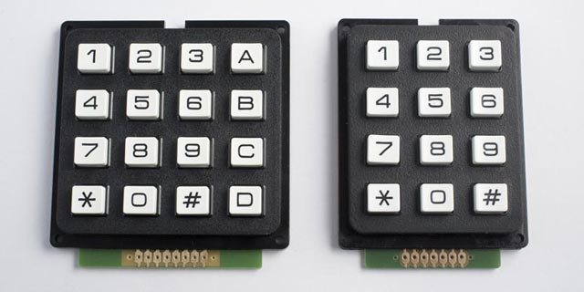
The keys on these keypads are arranged in a 3x4 or 4x4 matrix, and the usual way to interface to them takes seven or eight I/O pins, using multiplexing. I was interested in whether it would be possible to interface a pushbutton matrix to a single analogue input, using a resistor ladder in a similar way to my earlier post Getting Extra Pins on ATtiny.
Using a modified version of the program I used to find resistor ladder values I was pleased to find a configuration that would indeed give 16 different voltage outputs for the keys, using just seven standard E6 resistors. Here's how it works:
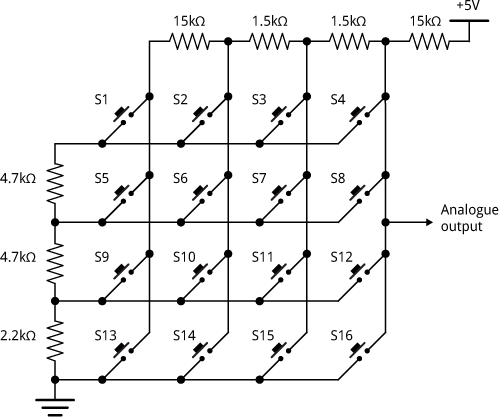
These resistor values give the largest possible difference between successive voltages, to make the design as tolerant of variations in the resistor values as possible. The ADC value given for each switch is shown in the following table:
| Switch | None | 1 | 2 | 3 | 4 | 5 | 6 | 7 | 8 | 9 | 10 | 11 | 12 | 13 | 14 | 15 | 16 |
| Value | 1023 | 679 | 505 | 477 | 446 | 639 | 407 | 367 | 322 | 587 | 263 | 202 | 130 | 558 | 170 | 93 | 0 |
The smallest gap between any pair of values is 28.
Sample program
Here's a circuit I prototyped to test the 16-key keypad interface:
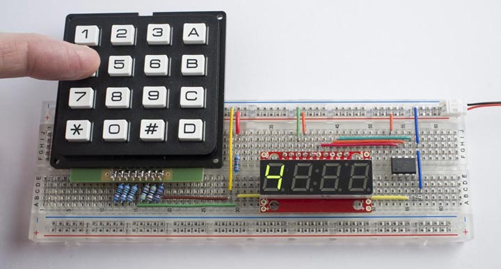
The resistor ladder is connected to the analogue input A2 on an ATtiny85. I'm using a serial seven-segment display [4] to display the key pressed; this is interfaced to three pins on the ATtiny85, using Jack Christensen's tinySPI interface [5].
Here's the program. It uses two arrays; AnalogVals[] stores the analogue values given by each pin, in descending order, and Buttons[] stores the corresponding button for each voltage. The ReadButton() routine reads the analogue input, and then checks the value against each value in AnalogVals[] until it's larger; it then returns the corresponding button from Buttons[].
/* Matrix Keyboard */

#include <tinySPI.h>               //http://github.com/JChristensen/tinySPI
#define HARDWARE_SPI 1

// SPI setup
const int LATCH_PIN = 0;           //storage register clock (slave select)
const int DATA_PIN = 1;            //data in
const int CLOCK_PIN = 2;           //shift register clock

// Matrix setup
const int SmallestGap = 28;
const int nButtons = 16;
int AnalogVals[] = {1023, 679, 639, 587, 558, 505, 477, 446,
                     407, 367, 322, 263, 202, 170, 130,  93,  0};
int Buttons[] =    {0,    '1', '4', '7', 'E', '2', '3', 'A',
                     '5', '6', 'B', '8', '9', '0', 'C', 'F', 'D'};

void setup(void) {
    SPI.begin();
    SPI.setDataMode(0);
    pinMode(LATCH_PIN, OUTPUT);
    digitalWrite(LATCH_PIN, HIGH);
}

// Returns the button character or 0 if no button pressed
char ReadButton() {
  int val = analogRead(A2) + SmallestGap/2;
  for (int i=0; i<=nButtons; i++) {
    if (val >= AnalogVals[i]) return Buttons[i];
  }
}

void loop(void) {
   digitalWrite(LATCH_PIN, LOW);
   SPI.transfer(0x76); // Clear display
   int b = ReadButton();
   if (b != 0) SPI.transfer(b);
   digitalWrite(LATCH_PIN, HIGH);
   delay(100);
}
Note that I've changed '*' and '#' to 'E' and 'F' because the 7-segment display can't display those symbols.
12-Button keypad
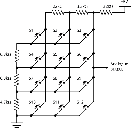
Here's the equivalent circuit for a 12-button keypad, using a ladder of six E6 resistors:
To use this with the above program change the matrix setup section to:
// Matrix setup
const int SmallestGap = 40;
const int nButtons = 12;
int AnalogVals[] = {1023, 680, 640, 590, 547, 507, 464,
                    411, 351, 273, 180, 133, 0};
int Buttons[] =    {0,    '1', '4', '7', '*', '2', '3',
                    '5', '6', '8', '9', '0', '#'};
Addendum
23rd January 2016: I've now written up details of the program I used to calculate sets of resistor values: Calculating a resistor network.
- ^ Keypad - 12 Button on Sparkfun
- ^ Keypad - 12 Button on Proto-PIC
- ^ Matrixed Data Keypad 3 x 4 on HobbyTronics
- ^ 7-Segment Serial Display on Sparkfun.
- ^ Arduino TinySPI Library on GitHub.
blog comments powered by Disqus