Pocket Op Amp Lab PCB
9th March 2021
This is a PCB version of my Pocket Op Amp Lab, a self-contained tool to allow you to experiment with the configurable op amps provided in the new AVR DB-series processors from Microchip:
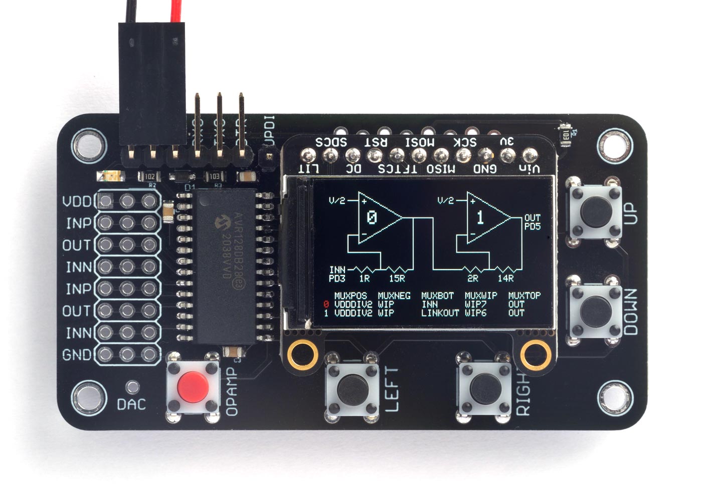
PCB version of the Pocket Op Amp Lab, which lets you interactively configure the op amps in an AV128DB28.
The board accommodates either an Adafruit 240x135 colour TFT display, or an equivalent display from AliExpress. I've included details, together with information about getting the PCBs, in case you want to build yourself a board.
For the original articles see Pocket Op Amp Lab and Pocket Op Amp Lab Cookbook.
The circuit
Here's the circuit of the PCB version:
Circuit of the PCB version of the Pocket Op Amp Lab.
It is based on the one in my original article, but with the following additions:
- There's an LED on PA7, the pin assigned to the Arduino built-in LED in the DxCore.
- There's a connector for an FTDI USB to Serial interface board, and the additional components to reset the board automatically.
- There's an additional pushbutton which can be used for a user-defined function.
► Parts list
Construction
I designed the PCB in Eagle, closely based on the layout of the prototype breadboard, and had a batch of boards made by PCBWay.
The AVR128DB28 is available in SPDIP (0.1" pin spacing), SOIC (0.05" pin spacing), and SSOP (0.025" pin spacing) packages. I chose to base the board on the SOIC package as it's relatively compact, but is not too small to solder by hand. My recommended approach is to use solder paste rather then wire solder. Put a blob of solder paste on each pad with a pin, and then lower the package into position with tweezers. Using a fine-tipped soldering iron melt the solder paste under two diagonally opposite corner pins, and check that you've got the package nicely centred. Then melt the paste under the remaining pins.
The resistor and capacitors are in 0805 packages, so they shouldn't be too difficult to solder by hand either.
Colour TFT display options
I've designed the board to accommodate two alternative 1.14" 240x135 colour TFT displays: either the Adafruit 240x135 colour TFT display [1], or one available from several vendors on AliExpress [2]. They both have an SPI interface which needs four I/O lines. The Adafruit one includes a regulator and level shifters, so you can use it with 3.3V or 5V; the AliExpress one is 3.3V only.
Here's the board with the AliExpress display:
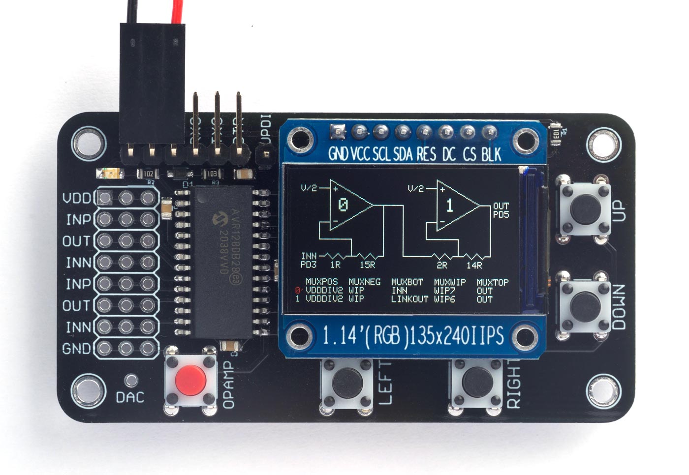
PCB version of the Pocket Op Amp Lab, showing the alternative colour TFT display from AliExpress.
Display header pins
The display is often the most expensive component in a project, and if you decide you want to reuse one in a different project it can be very difficult to unsolder the header pins. I therefore decided to try an idea from Microchip's latest Curiosity Nano boards. The header pin holes are staggered, with each hole shifted 8 mil (~0.2 mm) off-centre. This allows you to push the display's pin headers in place, and they will stay firmly connected without soldering. To remove them press evenly with a suitable flat object. Of course you also have the option of soldering them if you prefer, for a permanent solution.
Pushbuttons
Four through-hole pushbuttons are used for navigating the Op Amp Lab user interface. I've also provided a space for a fifth optional pushbutton which could be used as a shortcut for switching between the two op amps, or reassigned to other functions.
Op amp inputs and outputs
The six op amp inputs and outputs, and GND and VDD, are taken out to a 3x8 matrix of holes, and there are several options for what you do with these. You could leave them unpopulated, and use the area for soldering the external components you need in op amp applications. Alternatively, you could fit a 3x8 header socket [3], and use this as a prototyping area to plug in components without soldering. Finally, you could just connect a 1x8 header plug or socket, to allow you to connect patch leads to external circuits.
Compiling the program
Compile the programs using Spence Konde's Dx Core on GitHub.
Choose the AVR DB-series (no bootloader) option under the DxCore heading on the Board menu. Check that the subsequent options are set as follows (ignore any other options):
Chip: "AVR128DB28"
Clock Speed: "24 MHz internal"
Then upload the program to the AVR128DB28 using a UPDI programmer. The DxCore now supports the following two options:
- Make a UPDI programmer from an Arduino Uno, or other ATmega328P-based board, as described in Make UPDI Programmer, and set the Programmer option to "jtag2updi".
- Use a USB to Serial board, such as the SparkFun FTDI Basic board [4], connect TX to the UPDI pin via a 4.7kΩ resistor, connect RX directly to the UPDI pin, and set the Programmer option to "Serial port and 4.7k (pyupdi style)".
You can ignore the error "Cannot locate flash and boot memories in description".
If the display image is upside-down you need to uncomment the correct parameters for your display in the source before uploading it.
Resources
Here's the Pocket Op Amp Lab program, which is unchanged from the original version: Pocket Op Amp Lab Program.
Or get the program from GitHub, together with the Eagle files for the PCB so you can make yourself a board: https://github.com/technoblogy/op-amp-lab.
Or order boards from OSH Park here: Pocket Op Amp Lab.
Or order boards from PCBWay here: Pocket Op Amp Lab.
- ^ Adafruit 1.14" 240x135 Color TFT Display on Adafruit.
- ^ 1.14in SPI 240x135 RGB TFT display on AliExpress.
- ^ Female Header: 3x8-Pin, Straight on Pololu.com.
- ^ SparkFun FTDI Basic Breakout - 5V on Sparkfun.
blog comments powered by Disqus