GameBone Simple Electronic Game
23rd January 2017
The GameBone is a simple handheld electronic game constructed on a bone-shaped printed circuit board:
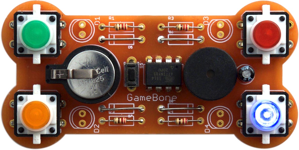
The ATtiny85-based GameBone handheld electronic game plays four different games.
It is based on an ATtiny85, and consists of four illuminated pushbuttons (or plain pushbuttons and LEDs), a reset button, a piezo buzzer, a battery, and four resistors. It plays a choice of four games, including Simon. If you're not already familiar with it, Simon plays a sequence of tones and lights, and you have to press the correct buttons to reproduce the sequence. At each round the sequence increases in length, and the aim is to reproduce the longest possible sequence without making a mistake. The GameBone also includes three other games: Echo, Quiz, and Confusion, and these are described below.
There have been several earlier designs for Simon games, including Sparkfun's kit [1], but I think I'm safe in saying that this is the simplest, with the fewest components. You could build it for about $10/£10, excluding the PCB.
The circuit
The circuit uses just four lines to control the LEDs and read the pushbuttons, allowing the use of the diminuitive ATtiny85 processor:
Circuit of the GameBone handheld electronic game.
As well as saving I/O lines, this circuit automatically lights up the corresponding LED when you press a button. To read the status of a pushbutton program the I/O line as an input, and to light a LED program the line as an output and leave it low. Note that you shouldn't program a pin as an output and take it high.
The components
For the buttons I used illuminated coloured pushbuttons with integral LEDs, available from Sparkfun [2], or from HobbyTronics in the UK [3], but I designed the circuit board so you could alternatively use plain 12mm square pushbuttons and coloured LEDs. There's also a reset button, which is a mini PCB bushbutton switch from Pololu [4].
The speaker is a small 12mm piezo buzzer, and the whole circuit is powered from a 3V CR1225 (or CR927) lithium button cell, mounted in a 12mm holder [5].
I designed the PCB in Eagle and sent it to Ragworm in the UK for manufacture [6]. It can be made as a single-sided board, making it suitable for a milling machine such as the Othermill [7] in which case four wire links need to be added to the board. Alternatively, with a double-sided board no links are needed:
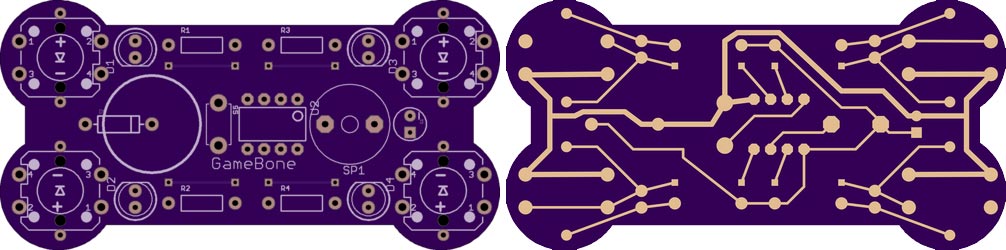
The final version of the PCB board design for the GameBone handheld electronic game.
The program
I developed an initial version of the Simon game in uLisp, my Lisp interpreter for the Arduino, running on an ATmega328; see Simon game. The C version described below is an extended version of this.
Play a note
To generate the tones used in the games the program uses a note() routine based on my project Simple Tones for ATtiny. This uses Timer/Counter1 to generate a tone on PB1, using a table of divisors scale[] to give the 12 notes of the scale, and the Timer/Counter1 prescaler to give the octaves:
const uint8_t scale[] PROGMEM = {239,226,213,201,190,179,169,160,151,142,134,127};

void note (int n, int octave) {
  DDRB = DDRB | 1<<DDB1;                     // PB1 (Arduino 1) as output
  int prescaler = 8 - (octave + n/12);
  if (prescaler<1 || prescaler>7) prescaler = 0;
  OCR1C = pgm_read_byte(&scale[n % 12]) - 1;
  TCCR1 = 1<<CTC1 | 1<<COM1A0 | prescaler;
}
The note function takes two parameters:
- A note number, from 0 to 11, representing the note in the well-tempered scale, where 0 represents C, 1 represents C#, and so on up to 11 for B.
- The octave, which can be from 1 to 7.
So to play middle C, C4, use:
note(0, 4);
To stop the note playing call note with two zero arguments:
note(0, 0);
Invalid octaves will have the same effect.
The note number can be greater than 11 as an alternative way of representing notes in higher octaves, so you could play C5 either with:
note(0, 5);
or with:
note(12, 4);
Flash a button
Each button has a fixed note associated with it. The notes are [8]:
- E4 (button 0, blue, lower right),
- C#4 (button 1, yellow, lower left),
- A4 (button 2, red, upper right),
- E3 (button 3, green, upper left).
The buttons and notes are defined by the arrays pins[] and notes[]:
// Buttons:    Blue   Orange Red    Green
int pins[] = { 2,     0,     3,     4};

// Notes:       E4  C#4 A4  E3
int notes[] = { 52, 49, 57, 40 };
The following two routines turn on and turn off a specified button:
void button_on (int button) {
  int p = pins[button];
  pinMode(p, OUTPUT);
  digitalWrite(p, LOW);
}

void button_off (int button) {
  int p = pins[button];
  pinMode(p, INPUT_PULLUP);
}
The flashbeep() routine flashes the button specified by its argument, and plays the corresponding note:
void flashbeep (int button) {
  button_on(button);
  note(notes[button], 0);
  delay(beat);
  note(0, 0);
  button_off(button);
}
Check for a button
To avoid the need for an on-off switch the GameBone automatically goes to sleep whenever it's waiting for a keypress. First a pin change interrupt is set up on the button inputs:
PCMSK = 1<<PINB0 | 1<<PINB2 | 1<<PINB3 | 1<<PINB4;
Then the routine to check for a button press, check(), enables the pin change interrupt and then puts the processor to sleep:
int check () {
  GIMSK = GIMSK | 1<<PCIE;            // Enable pin change interrupt
  sleep();
  GIMSK = GIMSK & ~(1<<PCIE);         // Disable pin change interrupt
  int button = 0;
  do {
    button = (button+1) % 4;
  } while (digitalRead(pins[button]));
  flashbeep(button);
  return button;
}
The pin change interrupt service routine is simply used to wake up the processor, and doesn't actually do anything:
ISR (PCINT0_vect) {
}
The check() routine then tests each input to see which button caused the interrupt, and returns it.
During sleep the current consumption is less than 1µA, giving an expected battery life of a few years.
The games
I have created four games for the GameBone, but it should be easy to invent your own and add them. To choose which game you want to play press the reset button, and when all four lights have flashed press the button corresponding to the game you want:
Simon (green)
This is the classic Simon game; the GameBone plays a sequence of tones and lights, and you have to press the correct buttons to reproduce the sequence. At each round the sequence increases in length, and the aim is to reproduce the longest possible sequence without making a mistake.
Here's the program:
void simon () {
  int turn = 0;
  sequence[0] = random(4);
  do {
    for (int n=0; n<=turn; n++) {
      delay(beat);
      flashbeep(sequence[n]);
    }
    for (int n=0; n<=turn; n++) {
      if (check() != sequence[n]) { fail_sound(); return; }
    }
    sequence[turn+1] = (sequence[turn] + random(3) + 1) % 4;
    turn++;
    delay(beat);
  } while (turn < maximum);
  success_sound();
}
Echo (red)
This is a two-player variant of Simon. The first player presses one button. The next player repeats that button and then adds another button. This continues, each player reproducing the sequence so far, and then adding another button to the end of the sequence before passing the GameBone to the other player. The first player to get the sequence wrong loses.
Here's the program, which is very similar to Simon:
void echo () {
  int turn = 0;
  sequence[turn] = check();
  do {
    for (int n=0; n<=turn; n++) {
      if (check() != sequence[n]) { fail_sound(); return; }
    }
    sequence[turn+1] = check();
    turn++;
    delay(beat);
  } while (turn < maximum);
  success_sound();
}
Unlike Simon, the Echo game allows you to press the same button two or more times in a row.
Quiz (orange)
This uses the GameBone for quiz games of up to 4 players. Each player has a button; the questionmaster reads a question out, and as soon as one player thinks they know the answer they press their button. Their tone sounds, and the light stays on for three seconds to confirm who got in first. The lights are then cleared ready for the next round.
Here's the program:
void quiz () {
  do {
    int button = check();
    button_on(button);
    delay(3000);
    button_off(button);
  } while (1);
}
Confusion (blue)
This game is like Simon for the first two rounds, but then it starts flashing the wrong light for all but the last note in the sequence. You have to copy the sequence of tones without being distracted by the false lights.
Here's the program:
void confusion () {
  int turn = 0;
  sequence[0] = random(4);
  do {
    for (int n=0; n<=turn; n++) {
      delay(beat);
      if (turn > 1 && n < turn) misbeep(sequence[n]);
      else flashbeep(sequence[n]);
    }
    for (int n=0; n<=turn; n++) {
      if (check() != sequence[n]) { fail_sound(); return; }
    }
    sequence[turn+1] = (sequence[turn] + random(3) + 1) % 4;
    turn++;
    delay(beat);
  } while (turn < maximum);
  success_sound();
}
Compiling the program
I compiled the program using Spence Konde's ATTiny Core, which supersedes the various earlier ATtiny cores [9]. Select the ATtinyx5 series option under the ATtiny Universal heading on the Boards menu. Then choose Timer 1 Clock: CPU, B.O.D. Disabled, ATtiny85, 1 MHz (internal) from the subsequent menus. This is the default fuse setting on new ATtiny85s; otherwise choose Burn Bootloader to set the fuses appropriately.
To upload the program I used Sparkfun's Tiny AVR Programmer Board; see ATtiny-Based Beginner's Kit. To connect the programmer board to the ATtiny85 on the GameBone I temporarily soldered two 4-way header sockets to the ATtiny85 pins on the bottom of the circuit board.
Here's the whole GameBone program: GameBone Program.
Alternatively, get it on GitHub here together with the Eagle files for the PCB: GameBone on GitHub.
Update
7th December 2020: The note() routine has been updated to leave the output in a high-impedance state when no note is playing, to avoid possible noise from the speaker, as in the update to Playing Notes on the ATtiny85. Thanks to skudave for suggesting this.
- ^ SparkFun Simon Says - Through-Hole Soldering Kit on SparkFun.
- ^ LED Tactile Button - Red on SparkFun.
- ^ LED Tactile Button - Red on HobbyTronics.
- ^ Mini PCB Pushbutton Switch on HobbyTronics.
- ^ Keystone PCB Mount Battery Holder for 12mm Coin Cell on RS Online.
- ^ Ragworm PC prototyping service.
- ^ Othermill Pro on Other Machine Co.
- ^ Simon (game) on Wikipedia
- ^ ATTinyCore on GitHub.
blog comments powered by Disqus