Tiny Function Generator PCB
7th February 2019
This is a PCB version of my earlier Tiny Function Generator project based on an ATtiny85. It uses Direct Digital Synthesis to generate sine, triangle, sawtooth, square, and rectangular waves, a pulse train, and noise. The frequency can be adjusted using a rotary encoder between 1Hz and 5kHz in steps of 1Hz, and the selected waveform and frequency is displayed on an OLED display:
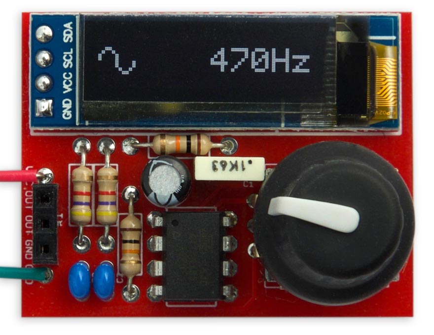
Tiny Function Generator PCB, based on an ATtiny85.
The original article Tiny Function Generator included seven waveforms, and the follow-up article Tiny Function Generator Sine Wave added the sine wave.
Waveforms
The Tiny Function Generator provides the following ten waveforms, which you can step between by pressing the rotary encoder button:
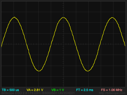 Sine Wave
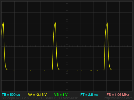
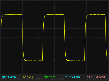 Square Wave
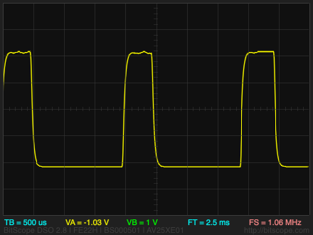 Rectangular Wave
 Pulse Train
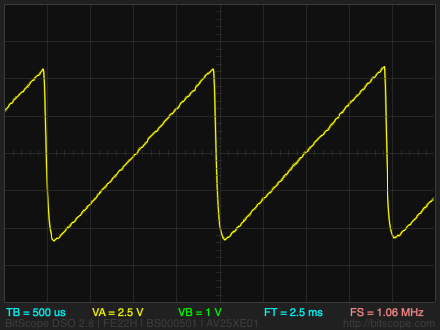 Sawtooth Wave
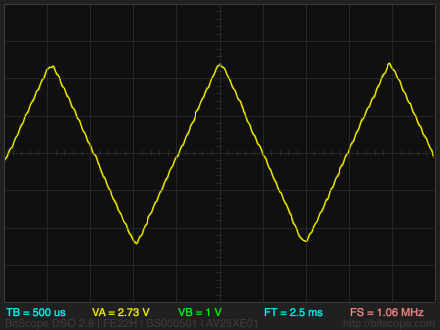 Triangle Wave
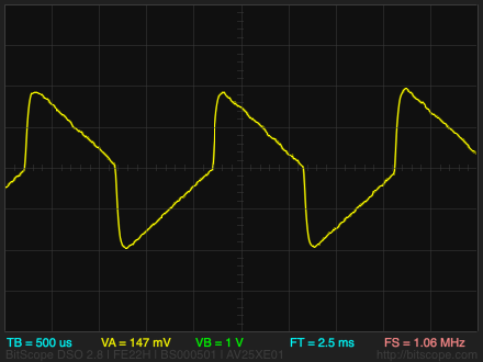 "Chainsaw" Wave
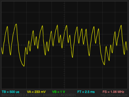 Noise
Noise
For each waveform (except the noise) you can adjust the frequency by turning the rotary encoder. An icon representing the currently selected waveform, and the frequency in Hz, are shown on the OLED display.
The circuit
Here's the circuit of the Tiny Function Generator PCB:
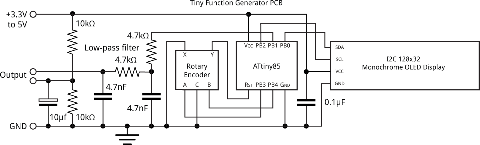
Circuit of the ATtiny85-based Tiny Function Generator.
Because the output at PB1 varies between 0V and +5V there's a +2.5V DC offset on the waveforms. The offset is avoided by taking the output relative to a virtual ground created by the two 10kΩ resistors.
► Parts list
Construction
Although I'm a fan of surface-mount, the rotary encoder and OLED display are through-hole, so in this case I decided to use through-hole components throughout to make it easier to construct the circuit without needing SMD experience.
I designed a board in Eagle and sent it to PCBWay for fabrication [1]. There's a link to the Eagle files at the end of the article if you want to make yourself a board.
The board is designed around a low-cost an OLED 128x32 I2C display module from AliExpress [2] held in place with a double-sided self-adhesive foam pad.
I programmed the ATtiny85 after I had soldered it onto the circuit board by piggy-backing an 8-pin IC socket on top of it, and then plugged in the wires from my Tiny AVR Programmer board. Alternatively you could program the ATtiny85 in the socket on the Tiny AVR Programmer board before soldering it in, or use an IC socket.
The program
For details of the program, and information about how to upload it to the ATtiny85, see the original article Tiny Function Generator.
Here's the whole Tiny Function Generator program: Tiny Function Generator PCB Program.
Alternatively, get it on GitHub here together with the Eagle files for the PCB: Tiny Function Generator on GitHub.
Or order a board from OSH Park here: Tiny Function Generator Board.
Updates
24th September 2019: Corrected circuit diagram (connections to rotary encoder), and program (comment about initial waveform).
19th December 2021: Changed the circuit diagram to move the virtual ground pin below the output pin, as on the PCB.
- ^ PCBWay PCB prototyping service.
- ^ 0.91 inch 128x32 I2C IIC Serial OLED LCD Display Module on AliExpress.
blog comments powered by Disqus