Pocket Op Amp Lab
12th January 2021
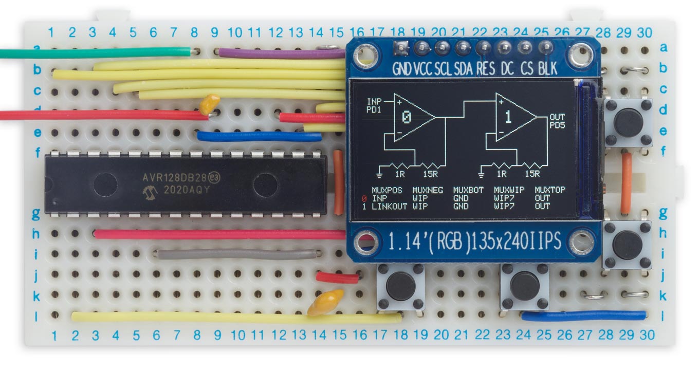
This is a self-contained tool to allow you to experiment with the configurable op amps provided in the new AVR DB-series processors from Microchip. It shows the configuration as a circuit diagram on the display, and lets you reconfigure it by selecting options from on-screen menus. The display is dynamically updated to reflect the configuration you have selected:
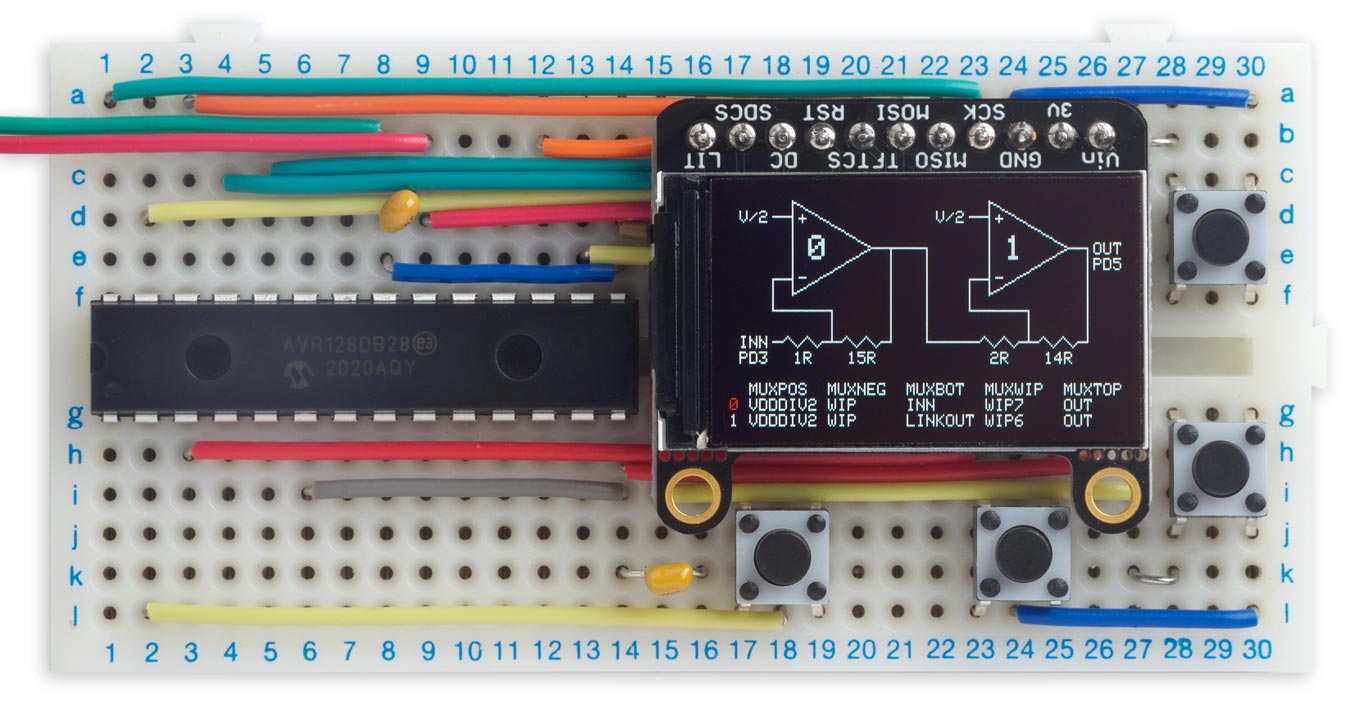
Pocket Op Amp Lab lets you interactively configure the op amps in an AV128DB28.
It's based on an Adafruit 240x135 colour TFT display, and an AVR128DB28 microcontroller. This provides two configurable op amps, each of which can be used to amplify low-level signals up to logic levels, or to process the output from the chip's DAC output. As you press the buttons to change a menu option, the op amp settings are also updated dynamically. So, for example, if you're using an op amp to amplify an audio signal you'll hear the volume change as you step between the MUXWIP options, which determine the op amp gain.
The Pocket Op Amp Lab Cookbook describes a series of projects based on the Pocket Op Amp Lab to demonstrate some interesting applications of the configurable op amps in the AVR DB series.
Introduction
One of the features I really like about the ATtiny85 that I've featured in many earlier projects is the programmable gain on the ADC channels, which allows you to create projects that amplify low-level signals like my ATtiny85 Sound Level Meter and Tiny Thermocouple Thermometer. I was therefore very excited when Microchip announced that their DB series include programmable op amps, which allow you to do this and a whole lot more.
Microchip provide an excellent set of tools for configuring the op amps and analysing their performance [1]. However, the idea of having a self-contained op amp laboratory appealed to me, to allow you to interactively configure them and see the results. I've learnt a lot by playing around with this project, and I hope you find it interesting too!
How it works
The two op amps in the AVR128DB28 are configured using five register fields. The fields have names such as MUXPOS, where "MUX" means "multiplexer", another name for an electronic switch, and "POS" identifies the op amp connection being switched, in this case the positive input.
The five register fields are:
- MUXPOS: the op amp's positive (non-inverting) input.
- MUXNEG: the op amp's negative (inverting) input.
- MUXBOT: the bottom of the resistor ladder.
- MUXWIP: the resistor ladder wiper position. The resistors always add up to 16R, and this determines the relative values.
- MUXTOP: the top of the resistor ladder.
Register field values
Each register field can be set to one of the following values to specify where the corresponding connection should be switched:
| Menu | Option | Description |
| MUXPOS | INP | The INP pin for the op amp |
| WIP | The wiper from the op amp's resistor ladder | |
| DAC | The DAC output | |
| GND | Ground | |
| VDDIV2 | VDD/2 | |
| LINKOUT | The output from the previous op amp | |
| LINKWIP | Not available | |
| MUXNEG | INN | The INN pin for the op amp |
| WIP | The wiper from op amp's resistor ladder | |
| OUT | The op amp's output | |
| DAC | The DAC output | |
| MUXBOT | OFF | No connection |
| INP | The INP pin for the op amp | |
| INN | The INN pin for the op amp | |
| DAC | The DAC output | |
| LINKOUT | The output from the previous op amp | |
| GND | Ground | |
| MUXWIP | WIP0 | 15R, 1R |
| WIP1 | 14R, 2R | |
| WIP2 | 12R, 4R | |
| WIP3 | 8R, 8R | |
| WIP4 | 6R, 10R | |
| WIP5 | 4R, 12R | |
| WIP6 | 2R, 14R | |
| WIP7 | 1R, 15R | |
| MUXTOP | OFF | No connection |
| OUT | The op amp's output | |
| VDD | VDD |
The Pocket Op Amp Lab provides an equivalent set of menus to let you configure the op amps. The settings for op amp 0 are shown on the row labelled 0 in the left column, and the settings for op amp 1 are on the row labelled 1. The currently selected option is shown in red.
Initial configuration
When the program starts, the inputs and outputs are connected to the INP, INN, and OUT I/O pins, and the resistors are not connected. This allows you to use the op amps as stand-alone circuits by connecting external components:
The op amps configured as stand-alone circuits.
See the circuit diagram below for information about which pins INP, INN, and OUT correspond to for each op amp.
The Pocket Op Amp Lab provides four buttons to let you change the configuration, and the currently selected menu option is highlighted in red. The Left and Right buttons step between menus, and the Up and Down buttons change the setting of the currently highlighted menu.
To choose which op amp to configure
- Press Left or Right to highlight the 0 or 1 in the leftmost column.
- Press Up or Down to highlight the op amp you want to configure.
To change a setting for an op amp
- Press Left or Right to highlight the current value of the setting you want to change.
- Press Up or Down to step between the available values.
The diagram will update dynamically to show the new configuration, and the op amps will be configured so you can measure the change in the circuit.
For example, to link the output of op amp 0 to the positive input of op amp 1, highlight INP in the 1 row and MUXPOS column, and press down twice to select LINKOUT. The display will change to:
The output of op amp 0 connected to the positive input of op amp 1.
The current settings are automatically saved to the EEPROM on the AVR128DB28, so when you next power up the Pocket Op Amp Lab the settings will be reset to the last configuration you created.
Possible configurations
Some examples of configurations you can make are: voltage follower, non-inverting amplifier with gain, inverting amplifier with gain, differential amplifier, and two-stage amplifier. These and others are given in the AVR128DB28/32/48/64 datasheet [2], and I'll describe them in a follow-up article. For example, here's the configuration for a two-stage amplifier:
The op amps configured as a two-stage amplifier with programmable gain.
The total gain can be adjusted up to 225 by changing the resistor settings; in the above configuration it's (15/1) x (14/2) or 105.
The circuit
Here's the circuit of the Pocket Op Amp Lab, reflecting the layout on the breadboard:
Circuit of the Pocket Op Amp Lab, based on an AV128DB28.
The processor is an AVR128DB28 in a SPDIP package [3], and the display is an Adafruit 240x135 colour TFT display with an SPI interface [4], available from Pimoroni in the UK [5]. For the pushbuttons I used 6mm square through-hole pushbuttons [6].
Microchip seem to be recommending 1µF decoupling capacitors in their latest datasheets, but I'm sure the circuit will work fine with the usual 100nF capacitors.
I built the whole circuit on a 360 hole breadboard [7] as usual using Pololu pre-cut jumper wires, available from HobbyTronics in the UK [8].
Using the AliExpress TFT display
I've also tested the circuit with a similar colour TFT 240x135 display available from several vendors on AliExpress [9]:
Pocket Op Amp Lab using a 240x135 colour TFT display from AliExpress.
Note the following points about this display:
- To use the display uncomment the appropriate line at the start of the Pocket Op Amp Lab listing.
- The display is 3.3V only, so if you're using it don't power the Pocket Op Amp Lab with more than 3.3V.
- The display requires a pullup of about 10kΩ to VDD on the Reset pin, otherwise it won't work.
The program
Graphics interface
The graphics interface to the TFT display is based on my Compact TFT Graphics Library. For convenience I've defined a point type, which uses a struct to store the x and y coordinates of a point in a single value:
typedef struct {
  int x;
  int y;
} point;
The following definitions overload the '+' and '-' operators to perform vector addition and subtraction with points:
point operator+ (const point &lhs, const point &rhs) {
  point temp;
  temp.x = lhs.x + rhs.x;
  temp.y = lhs.y + rhs.y;
  return temp;
}

point operator- (const point &lhs, const point &rhs) {
  point temp;
  temp.x = lhs.x - rhs.x;
  temp.y = lhs.y - rhs.y;
  return temp;
}
The op amp diagram
To make the op amp diagram easier to construct, the graphics are organised on a character-sized grid of 40x15 character cells, each of which is 6x9 pixels. These dimensions are given by the constants cx and cy.
Characters are drawn in integral grid positions, and the macro Grid is provided to convert between a grid position and screen coordinates for each of the Op Amp positions, specified by opn:
#define Grid(opn, x, y) (point){(opn*20+(x))*cx, (y)*cy}
Lines are drawn between the centres of the character cells (with a few exceptions), and the macro GridX converts between these positions and screen coordinates:
#define GridX(opn, x, y) (point){(opn*20+(x))*cx+2, (y)*cy+4}
This approach should make it relatively easy to scale the project to a larger display, such as a 320x240 TFT display, or to accommodate the three op amps in the 48-pin and 64-pin members of the AVR DB series.
Menus
The menus are defined by an array of structs, defined by the following menu_t type:
typedef struct {
  const char name[7];
  uint8_t options;
  register8_t *reg;
  uint8_t mask;
  uint8_t position;
  const char **values;
  fn_ptr_t drawfn;
} menu_t;
Here's the definition of the menus:
const menu_t Menus[nMenus] = {
//Name Options Reg              Mask             Position         Values  Drawfn
{"",       2, 0,                0,               0,               OpAmps, 0},
{"MUXPOS", 7, &OPAMP.OP0INMUX,  OPAMP_MUXPOS_gm, OPAMP_MUXPOS_gp, MuxPos, MuxPosFn},
{"MUXNEG", 4, &OPAMP.OP0INMUX,  OPAMP_MUXNEG_gm, OPAMP_MUXNEG_gp, MuxNeg, MuxNegFn},
{"MUXBOT", 6, &OPAMP.OP0RESMUX, OPAMP_MUXBOT_gm, OPAMP_MUXBOT_gp, MuxBot, MuxBotFn},
{"MUXWIP", 8, &OPAMP.OP0RESMUX, OPAMP_MUXWIP_gm, OPAMP_MUXWIP_gp, MuxWip, MuxWipFn},
{"MUXTOP", 3, &OPAMP.OP0RESMUX, OPAMP_MUXTOP_gm, OPAMP_MUXTOP_gp, MuxTop, MuxTopFn}
};
For each menu, the Menus array specifies the following fields:
- name: the text to be displayed on the menu.
- options: the number of options on the menu.
- reg: the address of the corresponding register in the op amp peripheral.
- mask: the bit mask for the option's field in that register.
- position: the position of the field in the register.
- values: an array of strings specifying the name of each option.
- drawfn: a function that is called to draw the effect of changing the selected option on the menu.
The actual options are specified by an array of strings; for example for MUXTOP they are:
const char *MuxTop[3] = {"OFF ", "OUT ", "VDD "};
Changing a menu option
When you change the value of a menu option, the program first sets the foreground colour to black and calls its drawfn with the previous option value, to erase it from the diagram. It then sets the foreground colour to white and calls the drawfn with the new option value, to draw it on the diagram.
As an example, here's the drawfn for MUXTOP:
void MuxTopFn (uint8_t opn, uint8_t index) {
  if (index == 1) { // OUT
    MoveTo(Top(opn) + (point){0, 1}); DrawTo(Out(opn) - (point){0, 1});
    if (State[opn][MUXNEG] == 2 && fore == BlackColour) { // Redraw MuxTop OUT
      fore = WhiteColour;
      MuxNegFn(opn, 2);
    }
  } else if (index == 2) { // VDD
    MoveTo(TopLabel(opn)); PlotText("VDD");
  }
}
Option 0, OFF, draws nothing, and Option 2, VDD, labels the top of the resistor ladder with VDD.
Option 1, OUT, draws a line between the top of the resistor ladder and the op amp's output. This line overlaps the line representing the MUXNEG OUT option, so this option calls that function again to redraw the erased line.
The options on the other menu options are implemented in a similar way.
Configuring the AVR128DB28
The op amp peripheral in the AVR128DB28 is initially configured by calling InitOpAmp(), which sets the timebase for a 24MHz clock, and enables the op amps:
void InitOpAmp () {
  // Set up the timebase
  OPAMP.TIMEBASE = 23; // Number of CLK_PER cycles in 1 us, minus one
  OPAMP.OP0CTRLA = OPAMP_OP0CTRLA_OUTMODE_NORMAL_gc | OPAMP_ALWAYSON_bm;
  OPAMP.OP1CTRLA = OPAMP_OP1CTRLA_OUTMODE_NORMAL_gc | OPAMP_ALWAYSON_bm;
  OPAMP.CTRLA = OPAMP_ENABLE_bm;
}
The op amp registers are then configured by ConfigOpAmps(), which calls ConfigOpAmp() for each op amp and menu:
void ConfigOpAmp (uint8_t opamp, uint8_t menu, uint8_t state) {
  register8_t *Address;
  Address = Menus[menu].reg + OPAMPOFFSET * opamp;
  *Address = (*Address & ~(Menus[menu].mask)) | state<<(Menus[menu].position);
}

void ConfigOpAmps () {
  for (int i=0; i<nOpAmps; i++) {
    for (int j=1; j<nMenus; j++) {
      ConfigOpAmp(i, j, State[i][j]);
    }
  }
}
The address of each register, and the position and bit mask for each register field, are read from the Menus[] structure.
The buttons
Each of the buttons is connected to an I/O pin on the processor, and the pins are configured to generate an interrupt on a falling input level:
void InitButtons () {
  pinMode(LeftBtn, INPUT_PULLUP);
  pinMode(RightBtn, INPUT_PULLUP);
  pinMode(UpBtn, INPUT_PULLUP);
  pinMode(DownBtn, INPUT_PULLUP);
  // Trigger buttons on falling level
  PORTC.PIN0CTRL = PORTC.PIN0CTRL | PORT_ISC_FALLING_gc;
  PORTC.PIN1CTRL = PORTC.PIN1CTRL | PORT_ISC_FALLING_gc;
  PORTF.PIN0CTRL = PORTF.PIN0CTRL | PORT_ISC_FALLING_gc;
  PORTF.PIN1CTRL = PORTF.PIN1CTRL | PORT_ISC_FALLING_gc;
}
The advantage of using interrupts is that the user interface will continue to be available whatever task the main program is performing.
Two interrupt service routines respond to the interrupts from the buttons, and implement the change to the user interface. For example, here's the interrupt service routine for the left and right buttons, which switch between menus:
ISR(PORTC_PORT_vect) {
  // Debounce buttons
  static unsigned long lastvisit;
  if (millis() - lastvisit < 250) {
    PORTC.INTFLAGS = PORT_INT0_bm | PORT_INT1_bm; // Clear interrupt flags
    return;
  }
  lastvisit = millis();
  // Step between menus
  int lr = (1 - digitalRead(RightBtn)) - (1 - digitalRead(LeftBtn));
  DrawMenu(OpAmp, Menu, State[OpAmp][Menu], false);
  Menu = (Menu + nMenus + lr) % nMenus;
  DrawMenu(OpAmp, Menu, State[OpAmp][Menu], true);
  PORTC.INTFLAGS = PORT_INT0_bm | PORT_INT1_bm; // Clear interrupt flags
}
The interrupt is ignored if it occurred too soon after the previous interrupt, to eliminate the effect of contact bounce.
Compiling the program
Compile the programs using Spence Konde's Dx Core on GitHub. I used version 1.2.0-a of the core which supports the DB-series, but it isn't compatible with Linux. This problem may be resolved in later versions; check on the GitHub repository.
Choose the AVR DB-series (no bootloader) option under the DxCore heading on the Board menu. Check that the subsequent options are set as follows (ignore any other options):
Chip: "AVR128DB28"
Clock Speed: "24 MHz internal"
Programmer: "jtag2updi (megaTinyCore)"
Then upload the program to the processor on the breadboard using a UPDI programmer connected to the GND, +5V, and UPDI pins. You can make a UPDI programmer from an Arduino Uno, or other ATmega328P-based board, as described in Make UPDI Programmer.
The program should also work on lower-memory versions of the AVRxxDB28-series, and at other clock speeds.
Here's the whole Pocket Op Amp Lab program: Pocket Op Amp Lab Program.
Or get it from GitHub at: https://github.com/technoblogy/op-amp-lab.
Further suggestions
Here are some additional ideas you could incorporate into the Pocket Op Amp Lab:
- I haven't really made much use of the colour available on the TFT display. You could use this to identify different types of information on the diagram.
- The program could also be extended to work with the three op amps in the larger AVR DB-series 48-pin and 64-pin parts, but you'd ideally need to find a display that's at least 360 pixels wide.
- ^ Getting Started with Analog Signal Conditioning on Microchip.
- ^ AVR128DB28/32/48/64 datasheet on Microchip.
- ^ AVR128DB28-I/SP on Farnell.
- ^ Adafruit 1.14" 240x135 Color TFT Display on Adafruit.
- ^ Adafruit 1.14" 240x135 Color TFT Display on Pimoroni.
- ^ Alcoswitch FSM4JH Tactile Switch on Farnell.
- ^ AD-100 Advanced Solderless Breadboard on Rapid Electronics.
- ^ 140 piece Jumper Wire Kit on HobbyTronics.
- ^ 1.14in SPI 240x135 RGB TFT display on AliExpress.
blog comments powered by Disqus