Tiny Face Watch
7th June 2017
This is the third in my series of minimalist watches based on the ATtiny85. This version displays the time by drawing an analogue watch face on a miniature 64x48 OLED display. It uses a separate crystal-controlled low-power RTC chip to keep time to within a few seconds a month, and puts the processor and display to sleep when not showing the time to give a battery life of over a year:
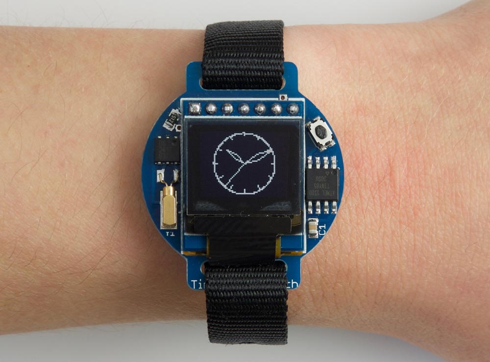
The Tiny Face watch based on an ATtiny85 and a 64x48 OLED display; it's ten past ten.
To show the time you press the button on the watch face, and it displays an analogue watch face on the display, with a moving seconds hand. The display is automatically blanked after 30 secs to preserve the battery life.
Introduction
Like my previous Tiny Time 2 Watch this watch is based on Maxim Integrated's DS2417 RTC chip, a small 6-pin package which uses a 32.768 kHz crystal to keep accurate time [1]. It can communicate with the main ATtiny85 processor via a 1-wire interface, which uses just one I/O pin to transmit and receive data. Because the RTC chip is doing the timing the ATtiny85 can stay asleep in power-down mode when it's not actually displaying the time, dramatically reducing the power consumption.
The display uses a small monochrome 64x48 OLED display with an SPI interface available from Aliexpress [2], or a similar one is available from Sparkfun [3]. The display needs 4 pins to drive it, just within the capabilities of the ATtiny85 leaving one pin free for the 1-Wire interface. You can't read the display memory, so to do graphics you need to write into a buffer in RAM, and then copy this to the display. Because the display is 64x48 pixels it requires 68x48/8 or 384 bytes of memory for the graphics buffer, again just within the capabilities of the ATtiny85.
The total power consumption with the display blanked is now about 8µA, giving an estimated battery life of over a year from a single CR2016 battery. Not quite as long as the Tiny Time 2 Watch, but still respectable.
The circuit
Here's the circuit of the Tiny Face watch:
Circuit of the ATtiny85-based Time Face watch.
The crystal is a standard 32.768 kHz quartz watch crystal; Maxell specify a 6pf load capacitance, and I chose a MS1V-T1K micro crystal which had the advantage that its case could be soldered to the board [4], but I expect any watch crystal would be suitable.
The button is a widely-available miniature SMD tactile switch, often used as a reset button on processor boards; I got mine from Farnell [5]. The 33kΩ resistor and 0.1µF capacitor ensure that the display is reset correctly when power is first applied.
The battery is a 20mm coin cell. Given the low current consumption I decided to use the slimmer CR2016 cell, and found a suitable SMD battery holder on Mouser [6]. Alternatively you could use a CR2032 battery, with an SMD 20mm coin cell holder available from Sparkfun [7], or from Proto-PIC in the UK [8].
The watch strap needs to be an 12mm thread-through type, and I found a suitable one from a German supplier [9]. I have also tried this cheaper alternative from a UK supplier [10], but note that this one is shorter and so may not be suitable if you don't have small wrists.
Construction
For this project I used Seeed Studio's PCB service [11], and chose blue PCBs to match the display. Here's the layout (from the OSH Park preview):
The watch uses SMD components, with all the components apart from the battery holder soldered to the front of the board. I used an SOIC ATtiny85 and 0805 resistors and capacitors, so they should be relatively easy to solder by hand. The DS2417 RTC chip is in a TSOC package, and is probably the trickiest item to solder as its legs are tucked under the package.
I used a Youyue 858D+ hot air gun at 250°C to solder the SMD components onto the front of the board, and then finally soldered the battery holder onto the back of the board using a conventional soldering iron. If you don't have a hot air gun you should be able to solder the SMD components with a bit of care using a fine-tipped soldering iron.
The following photographs show the front of the board before mounting the display, the board with the display, and the back of the board:
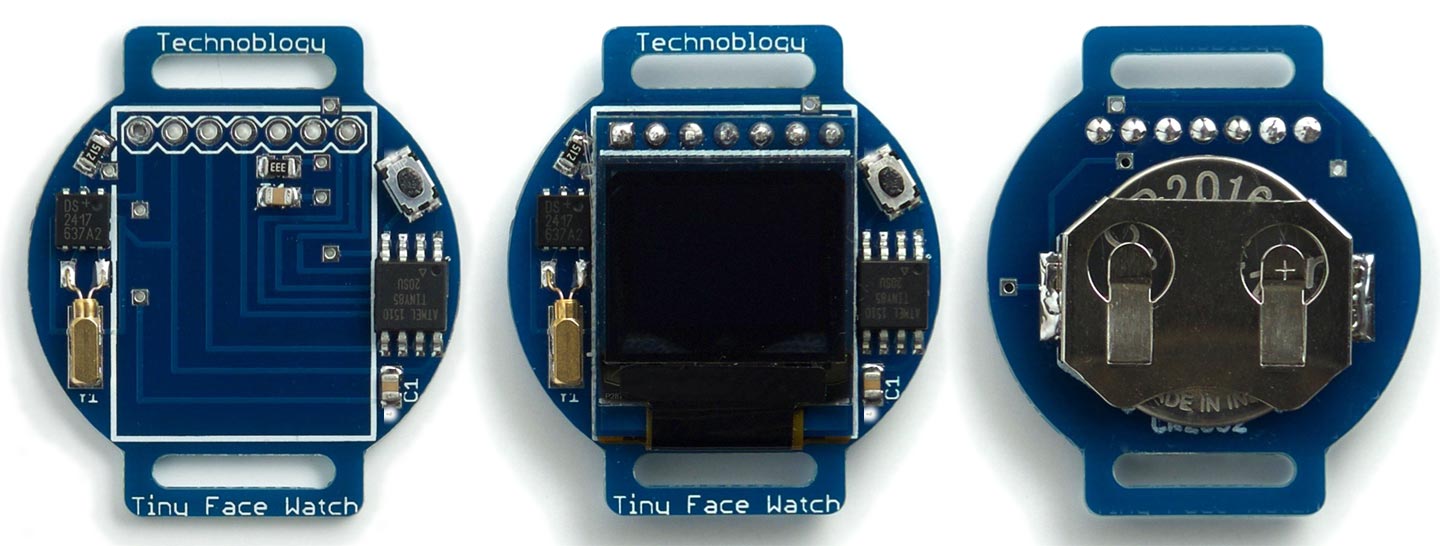
Assembling the Tiny Face watch circuit board.
I recommend testing the board before mounting the display on the board. You can access all the ATtiny85 pins needed for ISP programming, apart from RST, via the display's 7-pin connector.
The program
This section explains the various sections of the Tiny Face Watch program.
1-Wire interface
To communicate with the RTC I used the 1-Wire interface from my earlier article Simple 1-Wire Interface. It reads the five bytes of data from the RTC into an array DataBytes[5]. The first byte is a configuration byte, and the last four bytes give the number of seconds as a long integer; to make it easier I defined a union, so the time bytes can be accessed as rtc.seconds:
static union {
  uint8_t DataBytes[5];
  struct {
    uint8_t control;
    long seconds;
  } rtc;
};
The display
The display is based on my earlier article ATtiny85 Graphics Display. The clock face is drawn using graphics commands to draw lines, and these all edit a buffer which stores one bit for each pixel on the display. This is defined as follows:
// Screen buffer
const int Buffersize = 64*6;
unsigned char Buffer[Buffersize];
Once the clock face has been drawn into the buffer, the DisplayBuffer() routine display the contents of the buffer by copying the bytes to the display:
void DisplayBuffer () {
  PINB = 1<<cs; // cs low
  // Set column address range
  Command(0x21); Command(32); Command(95);
  // Set page address range
  Command(0x22); Command(2); Command(7);
  for (int i = 0 ; i < Buffersize; i++) Data(Buffer[i]);
  PINB = 1<<cs; // cs high
}
The SSD1306 is designed to handle displays up to 128x64, and the 64x48 display is positioned in the centre of this area, so to address it you need to select columns 32 to 95 (inclusive) and pages 2 to 7 (inclusive).
Drawing the clock
The routine DrawClock() draws the clock face and hand positions for a specified time, in hours, minutes, and seconds. It uses several tricks to avoid the need for trigonometric functions, and to minimise the number of multiplications and divisions needed. The routine essentially executes the following iterative routine 360 times to generate the points on a circle
x = x + Delta * y;
y = y - Delta * x;
where Delta is 1 degree in radians. The values of x and y are calculated using fixed-point arithmetic by storing them multiplied by a factor of 2^9.
void DrawClock (int hour, int minute, int second) {
  int x = 0; int y = 23<<9;
  for (int i=0; i<360; i++) {
    int x9 = x>>9; int y9 = y>>9;
    DrawTo(x9, y9);
    // Hour marks
    if (i%30 == 0) {
      MoveTo(x9 - (x9>>3), y9 - (y9>>3));
      DrawTo(x9, y9);
    }
    // Hour hand
    if (i == hour * 30 + (minute>>1))
      DrawHand(x9 - (x9>>2), y9 - (y9>>2));
    // Minute hand
    if (i == minute * 6 + second/10) DrawHand(x9, y9);
    // Second hand
    if (i == second * 6) {
      MoveTo(0, 0);
      DrawTo(x9, y9);
    }
    // Border of clock
    MoveTo(x9, y9);
    // if (x9 > 0) DrawTo(23, y9); else DrawTo (-23, y9);
    x = x + (y9 * Delta);
    y = y - ((x>>9) * Delta);
  }
}
It calls DrawHand() to draw the diamond-shaped hour and minute hands from 0,0 to x,y:
void DrawHand (int x, int y) {
   int v = x/2; int u = y/2;
   int w = v/5; int t = u/5;
   MoveTo(0, 0);
   DrawTo(v-t, u+w);
   DrawTo(x, y);
   DrawTo(v+t, u-w);
   DrawTo(0, 0);
}
The line plotting is performed by the DrawTo() line-drawing routine, which uses Bresenham's line algorithm to draw the best line between two points without needing any divisions or multiplications [12]
void DrawTo (int x1, int y1) {
  int sx, sy, e2, err;
  int dx = abs(x1 - x0);
  int dy = abs(y1 - y0);
  if (x0 < x1) sx = 1; else sx = -1;
  if (y0 < y1) sy = 1; else sy = -1;
  err = dx - dy;
  for (;;) {
    PlotPoint(x0, y0);
    if (x0==x1 && y0==y1) return;
    e2 = err<<1;
    if (e2 > -dy) {
      err = err - dy;
      x0 = x0 + sx;
    }
    if (e2 < dx) {
      err = err + dx;
      y0 = y0 + sy;
    }
  }
}
Setting the time
When you first apply power to the watch it checks the MCUSR register to detect a power-on reset, and runs SetTime() which allows you to set the time to the nearest second. It works as follows:
Wait until the current time is an exact minute, and insert the battery. The watch will then start from 12:00, stepping through the display one minute at a time. When the watch shows the time you inserted the battery (not the current time), press the reset button. The watch will account for the additional number of seconds it took you to set the time, and display the current time. It's now ready for use.
The SetTime() routine keeps incrementing the variable secs by 300, equivalent to five minutes, displaying the time for a second between steps. At each step it writes the value of secs to the RTC, with an offset added to account for the elapsed time since starting the procedure.
void SetTime () {
  unsigned long Offset = millis();
  unsigned long secs = 0;
  for (;;) {
    int Mins = (unsigned long)(secs / 60) % 60;
    int Hours = (unsigned long)(secs / 3600) % 12;
    // Write time to RTC
    rtc.control = 0x0C;
    rtc.seconds = secs + ((millis()-Offset)/1000);
    OneWireReset();
    OneWireWrite(SkipROM);
    OneWireWrite(WriteClock);
    OneWireWriteBytes(5);
    ClearBuffer();
    DrawClock(Hours, Mins, -1);
    DisplayBuffer();
    unsigned long Start = millis();
    while (millis()-Start < 500);
    secs = secs + 60;
  }
}
Displaying the time
The ATtiny85 is normally in sleep mode, which draws negligible current. The push button is connected to the reset input, which wakes the processor and generates a reset.
The main routine loop() first reads the time from the RTC into the variable secs:
  OneWireReset();
  OneWireWrite(SkipROM);
  OneWireWrite(ReadClock);
  OneWireReadBytes(5);
  OneWireReset();
  secs = rtc.seconds;
It then calculates the values of the variables Hours, Mins, and Secs, and displays an animated clock until SleepTime has elapsed (30 seconds):
  int Mins = (unsigned long)(secs / 60) % 60;
  int Hours = (unsigned long)(secs / 3600) % 12;
  int Secs = secs % 60;
  unsigned long Start = millis();
  unsigned long Now = Start;
  while (Now-Start < SleepTime) {
    ClearBuffer();
    DrawClock(Hours, Mins, (Secs + (Now-Start)/1000) % 60);
    DisplayBuffer();
    Now = millis();
  }
  DisplayOff();
  digitalWrite(dc,HIGH);
  digitalWrite(clk,HIGH);
  digitalWrite(data,HIGH);
  digitalWrite(cs,HIGH);
  pinMode(OneWirePin, OUTPUT); digitalWrite(OneWirePin,HIGH);
  sleep_enable();
  sleep_cpu();
It then turns the display off and sends the processor to sleep to minimise power consumption.
Other options
The clock face only occupies the central 48x48 pixels of the display, so there are two areas of 8x48 pixels on each side of the display that you could use to display other information. For example, you could use the temperature sensor on the ATtiny85 to measure the ambient temperature and display it graphically on one side of the display.
Compiling the program
I compiled the program using Spence Konde's ATTiny Core [13]. Choose the ATtiny25/45/85 option under the ATtinyCore heading on the Board menu. Then choose Timer 1 Clock: CPU, B.O.D. Disabled, ATtiny85, 8 MHz (internal) from the subsequent menus.
I programmed the ATtiny85 using Sparkfun's Tiny AVR Programmer Board; see ATtiny-Based Beginner's Kit. Choose Burn Bootloader to set the fuses appropriately, and then upload the program.
Here's the whole Tiny Face Watch program: Tiny Face Watch Program.
Alternatively, get it on GitHub here together with the Eagle files for the PCB: Tiny Face Watch on GitHub.
Or order a board from OSH Park here: Tiny Face Watch Board.
- ^ DS2417 1-Wire Time Chip with Interrupt on Maxim Integrated.
- ^ White 0.66 inch OLED Display Module 64x48 from e_goto Processors on Aliexpress.
- ^ SparkFun Micro OLED Breakout on Sparkfun.
- ^ MS1V-T1K 32.768kHz Micro Crystal on Farnell.
- ^ Multicomp MCIPTG23K-V Tactile Switch on Farnell.
- ^ BAT-HLD-002-SMT Linx Technologies Battery Holder on Mouser.
- ^ Coin Cell Battery Holder - 20mm (SMD) on SparkFun.
- ^ Coin Cell Battery Holder - 20mm (SMD) on Proto-PIC.
- ^ Watch strap 12mm black nylon/textile one-piece strap on Watchbandcenter.com.
- ^ Nylon - Easy Fit Thread-Through Nylon Watch Strap (8-16mm) on WatchBattery (UK) Ltd.
- ^ Fusion PCB on Seeed Studio.
- ^ Bresenham's line algorithm on Wikipedia.
- ^ ATTinyCore on GitHub.
blog comments powered by Disqus