Minimal Tiny I2C Routines
6th June 2018
This article describes a set of minimal I2C routines for ATtiny processors. They allow any ATtiny processor with a hardware USI to act as an I2C Master and connect to I2C peripherals. As an example of their use I've designed a digital clock circuit based on an ATtiny85 connected to an I2C RTC module and driving an I2C 7-segment display:
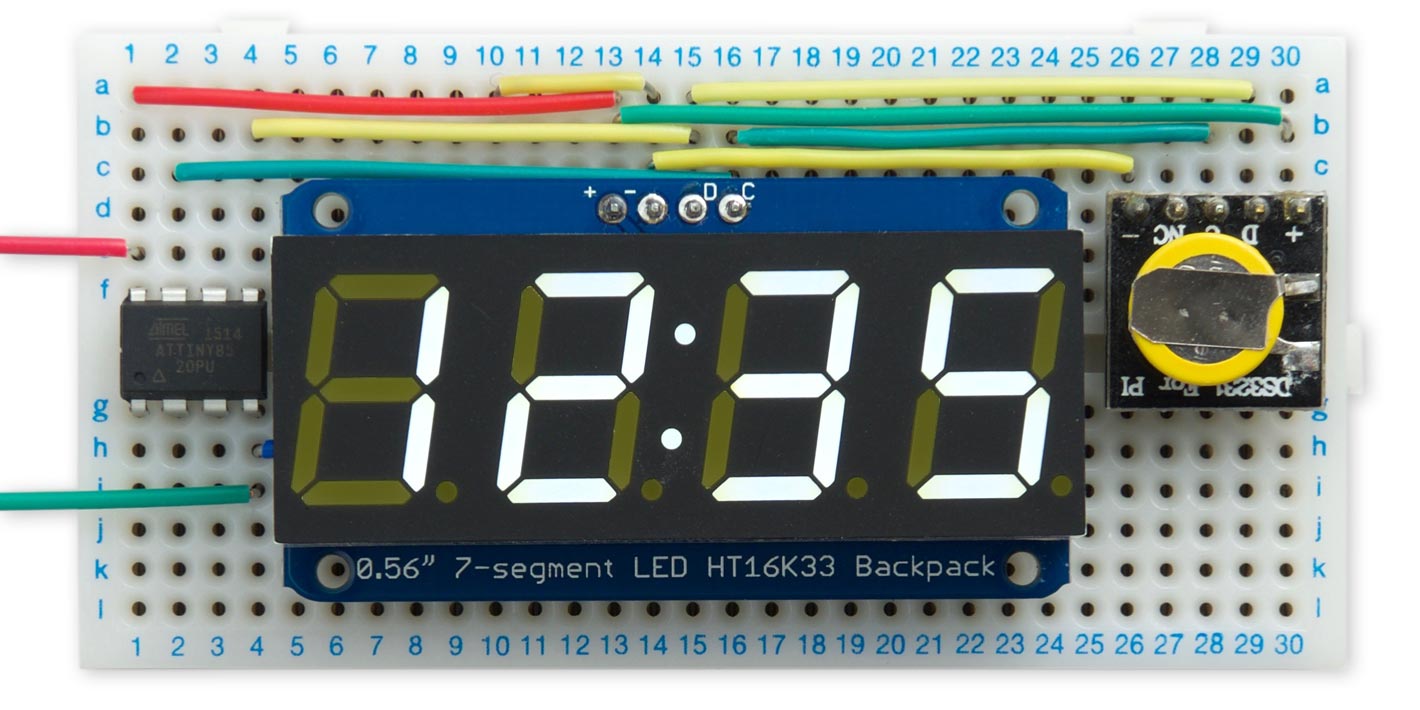
A simple I2C clock based on an ATtiny85 using the TinyI2C routines.
The main difference between these routines and most other Tiny Wire libraries is that these don't use buffers, so have minimal memory requirements, and don't impose a 32-byte limit on transmissions.
Introduction
I've named these routines TinyI2C for two reasons: to distinguish them from the existing TinyWire libraries, such as the one included in Spence Konde's ATTiny Core, and to emphasise that these routines don't follow the Arduino Wire library naming conventions.
In addition, these routines differ from the Tiny Wire library routines in the following ways:
Low memory requirements
These routines don't use buffers, reducing their RAM requirements to a couple of bytes. The standard Wire libraries use 32-byte send and receive buffers requiring 64 bytes, which isn't such a problem on the ATmega chips, but on an ATtiny85 this is a significant part of the available RAM.
I've always been puzzled about why the standard wire libraries use 32-byte send and receive buffers, and I haven't been able to find an answer to this on the web. As far as I can see there's no need for buffering as the I2C protocol incorporates handshaking, using the ACK/NACK pulses.
Unlimited transmission length
These routines don't impose any limit on the length of transmissions. The standard Wire libraries limit the length of any transmission to 32 bytes. This isn't a problem with many I2C applications, such as reading the temperature from a sensor, but it is a problem with applications such as driving an I2C OLED display, which requires you to send 1024 bytes to update the whole display.
Flexible read
These routines allow you to specify in advance how many bytes you want to read from an I2C peripheral, or you can leave this open-ended and mark the last byte read. This is an advantage when you don't know in advance how many bytes you are going to want to read.
Compatibility
Although so far I've only tested these routines on a couple of ATtiny chips, they should support all ATtiny chips with the USI peripheral, namely:
- ATtiny25/45/85
- ATtiny24/44/84
- ATtiny261/461/861
- ATtiny87/167
- ATtiny2313/4313
- ATtiny1634
These routines are based on the code described by Atmel Application Note AVR310 [1].
Description
Here's a description of the Minimal Tiny I2C routines:
TinyI2C.start(address, type)
Starts a transaction with the slave device with the specified address, and specifies if the transaction is going to be a read or a write. It returns true if the start was successful or false if there was an error.
The type parameter can have the following values:
- 0: Write to the device.
- 1 to 32767: Read from the device. The number specifies how many reads you are going to do.
- -1: Read an unspecified number of bytes from the device.
If type is specified as -1 you must identify the last read by calling TinyI2C.readlast() rather than TinyI2C.read().
TinyI2C.write(data)
Writes a byte of data to a slave device. It returns true if the write was successful or false if there was an error.
TinyI2C.read()
Returns the result of reading from a slave device.
TinyI2C.readLast()
Returns the result of reading from a slave device and tells the slave to stop sending. You only need to use TinyI2C.readlast() if you called TinyI2C.start() or TinyI2C.restart() with type set to -1.
TinyI2C.restart(address, type);
Does a restart. The type parameter is the same as for TinyI2C.start().
TinyI2C.stop()
Ends the transaction.
Examples
Writing to a slave
Writing to a slave is straightforward: for example, to write one byte:
TinyI2C.start(Address, 0);
TinyI2C.write(byte);
TinyI2C.stop();
Reading from a slave
The Minimal Tiny I2C routines allow you to identify the last byte read from a slave in either of two ways:
You can specify the total number of bytes you are going to read, as the second parameter of TinyI2C.start(). With this approach TinyI2C.read() will automatically terminate the last call with a NAK:
TinyI2C.start(Address, 2);
int mins = TinyI2C.read();
int hrs = TinyI2C.read();
TinyI2C.stop();
Alternatively you can just specify the second parameter of TinyI2C.start() as -1, and explicitly identify the last TinyI2C.read command by calling TinyI2C.readlast():
TinyI2C.start(Address, -1);
int mins = TinyI2C.read();
int hrs = TinyI2C.readLast();
TinyI2C.stop();
Writing and reading
Many I2C devices require you to write one or more bytes before reading, to specify the register you want to read from; the read should be introduced with an TinyI2C.restart() call; for example:
TinyI2C.start(Address, 0);
TinyI2C.write(1);
TinyI2C.restart(Address, 2);
int mins = TinyI2C.read();
int hrs = TinyI2C.read();
TinyI2C.stop();
Get the Tiny I2C Library from GitHub here: Tiny I2C Library.
I2C clock example
Here's one of the examples I used to test these routines; a simple digital clock using an I2C RTC module and an I2C 7-segment display.
The timekeeping is provided by an DS3231 RTC module [2], which is a low-cost, extremely accurate I2C real-time clock with an integrated temperature-compensated crystal oscillator. It also provides the date and two time of day alarms, although those features are not used in this application. Boards are available from several suppliers; I used one incorporating a backup battery from Seeed Studio [3], available from The Pi Hut in the UK [4].
For the display I used an I2C 7-segment display from Adafruit [5], available from Pimoroni in the UK [6]. It's available in a range of colours.
The circuit
The modules each connect to the ATtiny85 using four wires: Data to PB0/SDA (pin 5), Clock to PB2/SCL (pin 7), +5V to VCC (pin 8), and Gnd to GND (pin 4). I used the default I2C address for each device; 0x68 for the RTC, and 0x70 for the display.
Setting the time
The following SetClock() routine sets the time:
void SetClock (int hr, int min) {
  TinyI2C.start(RTCaddress, 0);
  TinyI2C.write(0);
  TinyI2C.write(0);
  TinyI2C.write(min);
  TinyI2C.write(hr);
  TinyI2C.stop();
}
The first call to I2Cwrite() sets the starting register to write to in the DS3231; in this case 0, the seconds register. We then set the seconds to 0, the minutes to min, and the hours to hr. The times are defined in binary-coded decimal, so to set the time to 12:34 you need to call:
SetClock(0x12, 0x34);
Once you have set the time the backup battery will keep the time correct in the DS3231, so you should comment out this line and upload the program again. From now on the time will always be correct, even if you interrupt power to the circuit.
The clock program
First we define the seven-segment display patterns for the digits 0 to 9:
char Segment[10] = {0x3F, 0x06, 0x5B, 0x4F, 0x66, 0x6D, 0x7D, 0x07, 0x7F, 0x6F};
Next the routine InitDisplay() initialises the display and sets the brightness to 1:
void InitDisplay () {
  TinyI2C.start(DisplayAddress, 0);
  TinyI2C.write(0x21);
  TinyI2C.restart(DisplayAddress, 0);
  TinyI2C.write(0x81);
  TinyI2C.restart(DisplayAddress, 0);
  TinyI2C.write(0xe1);
  TinyI2C.stop();
}
The last I2Cwrite() call sets the brightness, which can be from 0xe0 (off) to 0xef (maximum).
Finally, here's the main clock program:
void loop () {
  // Read the time from the RTC
  TinyI2C.start(RTCaddress, 0);
  TinyI2C.write(1);
  TinyI2C.restart(RTCaddress, 2);
  int mins = TinyI2C.read();
  int hrs = TinyI2C.read();
  TinyI2C.stop();

  // Write the time to the display
  TinyI2C.start(DisplayAddress, 0);
  TinyI2C.write(0);
  WriteWord(Segment[hrs / 16]);
  WriteWord(Segment[hrs % 16]);
  WriteWord(Colon);
  WriteWord(Segment[mins / 16]);
  WriteWord(Segment[mins % 16]);
  TinyI2C.stop();
  // Flash the colon
  Colon = 2 - Colon;
  delay(1000);
}
For each display digit you have to write two bytes to the display; this is for compatibility with Adafruit's other displays, and for this display the second byte is always zero. This is handled by WriteWord():
void WriteWord (uint8_t b) {
  TinyI2C.write(b);
  TinyI2C.write(0);
}
Curiously, the display is treated as having five digits, with the colon counted as the third digit, and to light it you have to write the value 2.
Here's the I2C clock example on GitHub: Tiny I2C Examples on GitHub.
Tiny Graphics Library
Finally, here's a version of my Tiny Graphics Library using these Minimal Tiny I2C routines; many of the routines are shorter, and consequently run faster, because there is no longer a 32-byte transmission limit.
Here's the Tiny Graphics Library on GitHub: TinyI2C Examples on GitHub.
Update
21st March 2019: I've fixed a bug in the TinyI2C library that prevented read from working correctly on the ATtiny44/84. I've checked the fixed version with the ATtiny85, ATtiny84, and ATtiny2313.
- ^ AVR310: Using the USI module as a TWI Master on Microchip.
- ^ DS3231 Datasheet on Maxim Integrated.
- ^ Mini RTC Module on Seeed Studio.
- ^ Mini RTC Module for Raspberry Pi on The Pi Hut.
- ^ Adafruit 0.56" 4-Digit 7-Segment Display w/I2C Backpack on Adafruit.
- ^ Adafruit 0.56" 4-Digit 7-Segment Display w/I2C Backpack on Pimoroni.
blog comments powered by Disqus