Portable Lab Power Supply
17th January 2016
This article describes a portable power supply, capable of providing from 0V to 5.5V at up to 1A, and powered by two rechargable Li-ion cells. The output can be adjusted using a rotary encoder, and the voltage is displayed on a three-digit 7-segment display. The whole circuit is controlled by an ATtiny861:
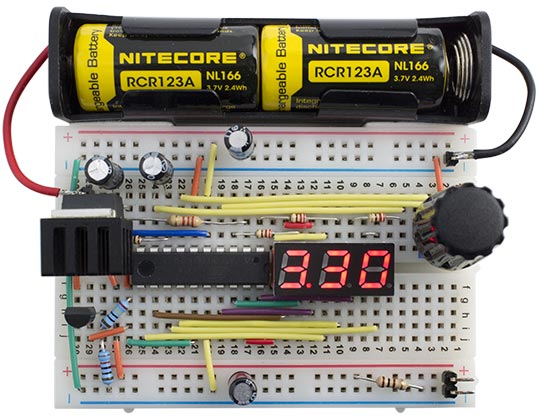
Portable lab power supply, supplies 0 to 5.5V at up to 1A.
For a development of this project see Proto Power Supply.
Specification
The project started when I decided that it would be very useful to have a lab power supply, to power my projects while I'm developing them. I had a look at some commercial products, but my workbench is a small desk, and I don't have room for a large mains-powered box. I therefore thought about building my own small portable power supply, powered from rechargable batteries, which wouldn't be tied to a power socket.
As the supply is designed for testing AVR projects I didn't need more than 5.5V, which is the maximum recommended voltage for AVR chips; in fact it's quite reassuring to know that the voltage cannot accidentally be turned up above this. This means that the supply could conveniently be powered by two 3.7V Li-ion batteries; I chose the compact RCR123A batteries with a capacity of 650mAH.
The power supply could have used a standard adjustable regulator, such as the LM317, but this only allows you to adjust the voltage down to 1.2V. I wanted to be able to adjust the voltage all the way down to zero. For example, if you're testing the behaviour of a circuit running from a dying battery you might want to slowly turn the voltage down to zero. Alternatively, you might want to find the voltage at which an LED lights up. I therefore chose the LT3080 by Linear Technology [1], a very nice device which provides up to 1.1A all the way down to zero, and provides short-circuit protection.
The supply allows you to adjust the voltage between 0V and 5.5V in steps of 0.02V using a rotary encoder, and it displays the actual voltage measured at the output terminals, using an analogue input; this ensures that when the output is shorted the display really does drop to zero, and also gives feedback if the batteries are getting low.
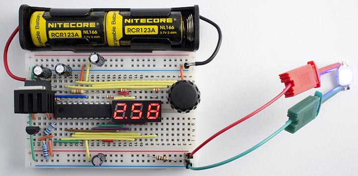
Using the portable lab power supply to test an LED.
Components
LT3080 regulator
The LT3080 is available in a variety of different packages. I chose the TO220-5 package which is easiest to mount on a prototyping board. To do this I splayed the leads apart to a 0.1" pitch, using a pair of long-nosed pliers. The leads are rectangular, and I also found that I needed to rotate the ends of the leads through 90° before they would fit in the prototyping board:
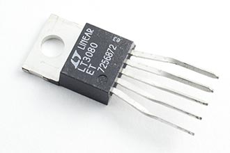
Bending the leads of an LT3080 to fit a prototyping board.
To generate the 5.5V to drive the digital circuitry and provide the reference for the ADC I used an LM371L adjustable regulator, which can be programmed with two resistors, as 5.5V isn't available from fixed regulators.
Rotary encoder
For the rotary encoder you could use Adafruit's rotary encoder, which gives 24 pulses per rotation [2], or Sparkfun's rotary encoder [3], which gives 12 pulses per rotation. Instead I used a miniature Bourns encoder, available from Farnell, which fits nicely in the prototyping board, and gives 16 pulses per revolution [4].
Processor
To drive the seven-segment three-digit display, with decimal point, we need 8 + 3 or 11 I/O lines. Then we need two digital inputs for the rotary encoder, one digital output for the PWM analogue output, and one analogue input to read the supply voltage, making a total of 15. I chose to base the project on the ATtiny861 which provides the required 15 I/O lines, and is perfect for this application. Alternatively, you could use the ATmega328, the basis of the Arduino Uno, but you'd need to modify my program slightly.
Display
The circuit uses a 0.28" 3-digit 7-segment LED display, bought on eBay from a supplier in Shenzhen for £1.30 for five! The displays I used are common-anode; to use common-cathode displays you will need to change the Display() routine.
Batteries
For the power input I chose two rechargable RCR123A batteries with a capacity of 650mAH, available from eBay. These include under- and over-charge protection, and so are slightly longer than standard CR123A batteries. I fitted them both in a single 18650 battery holder designed for longer protected batteries, available on eBay. Alternatively you could design your own PCB-mounted holder using two battery clips available from Sparkfun [5], or Proto-PIC in the UK [6].
Reading the rotary encoder
The rotary encoder is connected to two inputs, PB3 and PB4. These are configured to give pin-change interrupts in setup():
  PORTB = 1<<PORTB4 | 1<<PORTB3;       // Set input pullups
  PCMSK1 = 1<<PCINT12 | 1<<PCINT11;    // Configure pin change interrupts
  GIMSK = 1<<PCIE0 | 1<<PCIE1;         // Enable pin change interrupts
  GIFR = 1<<PCIF;                      // Clear pin change interrupt flag.
The pin-change interrupt service routine then reads the state of the two inputs, and determines which direction the rotary encoder has been turned:
ISR (PCINT_vect) {
  static int Laststate;
  // Debounce - wait for 4 identical readings
  int Last = -1, Count = 0, Gray;
  do {
    Gray = (PINB & 0x18)>>3;                 // Read PB3 and PB4
    Count++;
    if (Last != Gray) Count = 0;
    Last = Gray;
  } while (Count < 4);
  // Have now had 4 identical readings in a row
  int State = (Gray>>1) ^ Gray;              // Convert from Gray code to binary
  if (State != Laststate) {
    int Value = ((Laststate-State) & 3) - 2; // Gives -1 or +1
    ChangeValue(Value);
    Laststate = State;
  }
}
This is based on my earlier article Simple Rotary Encoder Interface, with the addition of some debounce code to give a precise number of pulses per rotation. This keeps reading the two inputs until they produce four successive identical values. With this improvement the change in Value is consistently 64 for a single rotation of the knob.
Generating an analogue output
The power supply voltage is set by an analogue output, generated by a PWM signal on PB1. This is generated using Timer/Counter1, which is configured in setup() to generate a PWM waveform with a mark-space ratio of between 0, giving a 0V output, and MaxVoltage-1 (or 549), giving a 5.49V output:
  TCCR1A = 2<<COM1A0 | 1<<PWM1A;
  TCCR1B = 2<<CS10;                    // Divide clock by 2 = 500kHz
  TC1H = (MaxVoltage-1) >> 8;          // High byte - count up to 500
  OCR1C = (MaxVoltage-1) & 0xFF;       // Low byte
  TIMSK = 1<<TOIE1;                    // Enable overflow interrupt
The mark-space ratio is specified by changing the value in OCR1A by calling ChangeValue():
void ChangeValue (int Change) {
  Voltage = max(min(Voltage + Change*Step, MaxVoltage), 0);
  TC1H = Voltage >> 8;                 // Set OC1A to voltage
  OCR1A = Voltage & 0xFF;
}
This gets called when the rotary encoder is rotated. The variable Step determines the rate at which the voltage changes. I chose the value 2, which allows you to adjust the voltage from 0V to 5.5V in about four turns of the rotary encoder.
Reading the output voltage
The regulated output voltage is read by the analogue input ADC8, on PB5. This is configured in setup() to use Vcc as the reference voltage:
  ADMUX = 0<<REFS0 | 8<<MUX0;          // Vcc as ref, ADC8 (PB5)
  ADCSRA = 1<<ADEN | 4<<ADPS0;         // Enable ADC, 62.5kHz clock
The analogue value is read by the routine ReadADC():
int ReadADC () {
  unsigned char low, high;
  ADCSRA = ADCSRA | 1<<ADSC;             // Start
  do ; while (ADCSRA & 1<<ADSC);         // Wait while conversion in progress
  low = ADCL;
  high = ADCH;
  return high<<8 | low;
}
Displaying the voltage
Finally, the analogue voltage is displayed on the three-digit 7-segment display. I used the same timer, Timer/Counter1, to multiplex the display. Every 550 counts the counter overflows, and this is used to call an interrupt service routine:
ISR (TIMER1_OVF_vect) {
  DisplayNextDigit();
}
This in turn calls DisplayNextDigit(). This puts the appropriate segment data onto PORTA for the next digit to be displayed, and then takes the digit common line high on PORTB. The number to be displayed on each display digit is specified by the array Buffer[]:
void DisplayNextDigit() {
  static int LastVoltage;
  DDRB = DDRB & ~(1<<Digits[digit]);         // Make digit bit an input
  digit = (digit+1) % (Ndigits+1);
  if (digit < Ndigits) {
    char segs = charArray[Buffer[digit]];
    if (digit==0) segs = segs | 0x80;        // Decimal point
    PORTA = ~segs;
    DDRA = segs;
    DDRB = DDRB | 1<<Digits[digit];          // Make digit bit an input
    PORTB = PORTB | 1<<Digits[digit];        // Take digit bit high
  } else {                                   // Read ADC
    DDRA = 0;
    // Scale to voltage*2
    int Voltage = (ReadADC() * (long) MaxVoltage)/512;
    // Add hysteresis to stop display jumping
    if (abs(LastVoltage - Voltage)>=2) {
      Display(Voltage>>1);
      LastVoltage = Voltage;
    }
  }
}
Every fourth cycle this routine also reads the ADC, and calls Display() to write the appropriate values to the display buffer, Buffer[]. This includes some code to prevent the display flickering between two adjacent values. It works by storing twice the value to be displayed, and then only changes the display if the value has changed by at least 2.
The circuit
Here's the full circuit of the portable lab power supply:
Circuit of the portable lab power supply, based on an ATtiny861.
The LT3080 requires a minimum load for the regulation to work properly, specified as about 500µA on the datasheet. The simplest way to provide this is to connect a resistor across the output; I chose 100Ω, which still gives a small reading of 0.02V with no load, but draws an additional 55mA at full voltage. See Variations below for suggested alternatives to this.
The circuit fitted neatly on a half-size breadboard [7] [8], with the LT3080 plugged into the board. I fitted a small heatsink to the LT3080 with thermal adhesive tape, but for continuous use at large currents it probably needs a more substantial heatsink.
I plan to transfer it to an equivalent-sized PCB [9] or piece of Veroboard, and mount it in a small case for permanent use.
Testing
The LT3080 is quite rugged, and includes over-temperature and short-circuit protection. However, it's still quite possible to destroy the device by connecting the input voltage to the wrong terminal, as I discovered to my cost. I recommend checking the processor side of the circuit first before connecting up the regulator, and double-check your connections carefully before applying power to the regulator.
Compiling the program
I compiled the program using the Arduino IDE with the ATTinyCore [10]. Select the ATtiny861 @ 1 MHz (internal oscillator; BOD disabled) option on the Boards menu. This is the default fuse setting on new ATtiny861s; otherwise choose Burn Bootloader to set the fuses appropriately. Then upload the program to the ATtiny861 using the Tiny AVR Programmer Board; see ATtiny-Based Beginner's Kit.
Here's the whole Portable Lab Power Supply program: Portable Lab Power Supply Program.
Update
1st December 2016: Corrected a couple of mistakes on the circuit diagram.
Variations
If you are happy with a maximum voltage of 5V you could use a fixed regulator, such as a 78L05, for the low-voltage supply. This avoids the need for the adjustment resistors. In this case change MaxVoltage to 500.
Instead of using a rotary encoder to adjust the supply voltage you could use a simple potentiometer, to apply a voltage between 0V and Vcc, in which case you can dispense with the pin change interrupt service routine and ChangeValue().
You could provide an additional "panic" button to turn the voltage to zero instantly, if the thing you're powering is misbehaving and you want to cut the power quickly. Some rotary encoders include a push-switch which could be used for this. You could also add push buttons to set the voltage to preset values, such as 3.3V, 5V, etc.
Instead of using a fixed 100Ω resistor as a load, some circuit designs use an LM334 to provide a constant current load of 1mA, to avoid wasting power at higher voltages.
To make the power supply work up to a higher voltage, such as 9V using three Li-ion cells in series, you would need to connect the ADC input via a voltage divider, to scale the voltage within range of the voltage reference, and use the PWM output to drive a MOSFET switch, switching a 9V reference voltage.
If you want to add current limiting, or a constant current option, you can use a second LT3080 to provide this; for more information see the Lab Supply application in the LT3080 Datasheet.
Some of these applications will require additional I/O lines. You could free up PB6 by driving the third display digit using PA7, since we don't need to display a decimal point in this position. You could also use the Reset pin as an analogue input, ADC10, provided you use a resistor divider to keep it above about 3V, to avoid triggering reset. Alternatively you could of course switch to a different processor, such as the ATmega328.
For an interesting discussion of portable power-supply design, and some alternative approaches to designing this type of power supply, I recommend Dave Jones's videos about his LT3080-based µSupply [11].
- ^ LT3080 Datasheet from Linear Technology.
- ^ Rotary Encoder + Extras on Adafruit.
- ^ Rotary Encoder on Sparkfun.
- ^ Bourns Rotary Encoder on Farnell.
- ^ Battery Holder - 18650 (PTH) on Sparkfun.
- ^ Battery Holder - 18650 (PTH) on Proto-PIC.
- ^ Half-size breadboard on Adafruit.
- ^ Breadboard - Self-Adhesive (White) on Sparkfun.
- ^ Adafruit Perma-Proto Half-sized Breadboard PCB on Adafruit.
- ^ ATtinyCore on GitHub.
- ^ µSupply in the Electronics Engineering Video Blog, EEVblog.
blog comments powered by Disqus