Infrared Controlled Buggy
20th July 2015
This article describes a simple buggy which you can control using an infrared remote control. It uses Lego for the motors and chassis, and is controlled by an ATtiny85:
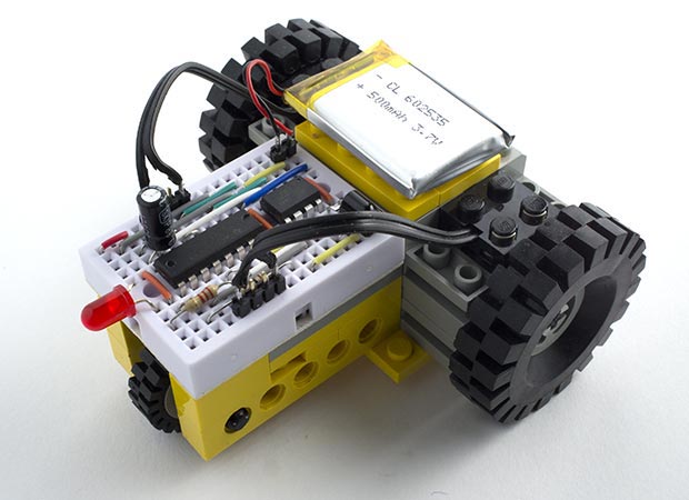
Infrared Controlled Buggy built from Lego, and controlled by an ATtiny85.
My eventual goal is to make a maze-solving robot, but as a first step I decided to build a buggy you could drive using an infrared control. I plan to develop this into a more intelligent robot.
To make the construction easier I decided to use standard Lego parts, and bought a cheap second-hand classic Lego Technic kit (model 8020) from eBay. To this I added two large wheels, two Lego Electric Technic Mini-Motors [1], and a connecting cable, again all from eBay. If you've got a collection of Lego you may already have all the parts you need.
Infrared control
For the infrared control I used the Adafruit remote control [2] (available from Proto-PIC in the UK [3]):
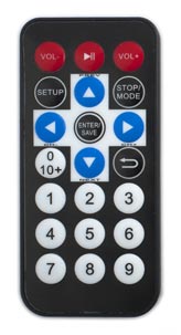
With the remote control you can change the buggy's speed, drive it forwards or in reverse, and steer it left or right. It can also turn on the spot, using the following buttons:
| Button | Function | Code |
| Up-Arrow | Go Forwards | 05 |
| Down-Arrow | Go Backwards | 0D |
| Left-Arrow | Turn Left | 08 |
| Right-Arrow | Turn Right | 0A |
| Stop/Mode | Stop | 06 |
| Enter/Save | Stop | 09 |
| Return | Rotate | 0E |
| 1 to 9 | Set Speed | 10 to 1A |
I discovered the remote control codes using my IR Remote Control Tool (NEC).
The circuit
Here's the circuit of the IR remote controlled buggy. It uses a 38kHz infrared receiver module available from Sparkfun [4], or from HobbyTronics in the UK [5] to receive the control commands:
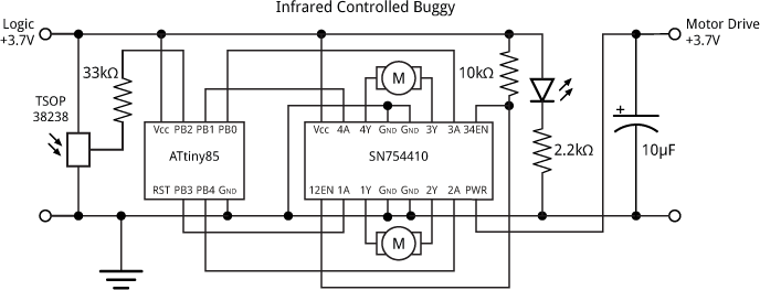
Circuit for the Infrared Controlled Buggy, using an SN754410 H-Bridge Motor Driver.
To drive the motors I used the breadboard-friendly SN754410 H-Bridge motor driver, which is capable of controlling two motors in forward or reverse with a current of up to 1A [6]. It's available from SparkFun [7], or Proto-PIC [8] or HobbyTronics [9] in the UK. For a good explanation of how the H-Bridge works see the Pololu site [10].
The enable pins 12EN and 34EN are pulled high via a 10kΩ resistor to permanently enable the motor drivers. The SN754410 allows you to provide a separate supply for the motors of up to 36V, and if you want your buggy to go faster the Lego motors will handle up to 9V, but for simplicity I powered the motors from the same 3.7V LIPO battery as the logic circuitry.
The 33kΩ resistor between the IR receiver and PB2 avoids errors when uploading programs to the ATtiny85 by isolating the output from the IR receiver from the ATtiny85. I included an LED to remind you that the battery is connected.
The whole circuit was built on a mini prototyping board:
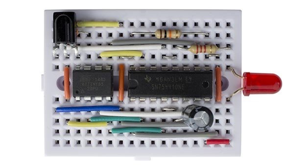
Control board for the Infrared Controlled Buggy.
The program
The infrared commands are interpreted by an ATtiny85, which also controls the speed of the motors using two PWM outputs.
The program decodes the pulses from the infrared receiver using an interrupt service routine, and this calls ReceivedCode() when a complete IR command has been received. The program to decode the remote-control codes is based on my earlier article IR Remote Control Receiver.
The ReceivedCode() routine then controls the motors according to the command received:
void ReceivedCode (boolean Repeat) {
  static int Left, Right, Speed = 127 ;
  // Check for correct remote control
  if ((RecdData & 0xFFFF) != 0xbF00) return;
  if (Repeat) return; // Ignore keys held down
  // Read key pressed
  int key = RecdData>>16 & 0xFF;
  // Motor commands
  if ((key >= 0x10) && (key <= 0x1A)) Speed = ((key - 16) * 12) + 7;
  else if (key == 0x05) { Left = 2; Right = 2; }                    // Go Forwards
  else if (key == 0x0D) { Left = -2; Right = -2; }                  // Go Backwards
  else if (key == 0x08) { Left = 2; Right = 1; }                    // Turn Left
  else if (key == 0x0A) { Left = 1; Right = 2; }                    // Turn Right
  else if ((key == 0x06) || (key == 0x09)) { Left = 0; Right = 0; } // Stop
  else if (key == 0x0E) { Left = 2; Right = -2; }                   // Rotate
  //
  if (Left >= 0) {
    digitalWrite(0, LOW);
    OCR1A = Left * Speed;
  } else {
    digitalWrite(0, HIGH);
    OCR1A = 255 + (Left * Speed);
  }
  if (Right >= 0) {
    digitalWrite(3, LOW);
    OCR1B = Right * Speed;
  } else {
    digitalWrite(3, HIGH);
    OCR1B = 255 + (Right * Speed);
  }
}
The statement:
Speed = ((key - 16) * 12) + 7;
sets the speed to between 7 and 127 depending on which number key 0 to 9 is pressed (I ignored the two gaps in the sequence of key codes for simplicity). The subsequent statements then set the direction of each motor depending on which direction key has been pressed.
To turn left or right the program drives one wheel at half the speed of the other one, and to rotate on the spot the program drives the wheels in opposite directions.
Timer/Counter0 is used for the IR receiver, so I used Timer/Counter1 to control the two motors. It is configured in setup() to generate a PWM output on OC1A (PB1) and OC1B (PB4) to control the speed of each motor:
TCCR1 = 1<<CTC1 | 1<<PWM1A | 2<<COM1A0 | 7<<CS10;
GTCCR = 1<<PWM1B | 2<<COM1B0;
Compiling the program
I compiled the program using the Arduino-Tiny core extension to the Arduino IDE [11]. Select the ATtiny85 @ 1 MHz (internal oscillator; BOD disabled) option on the Boards menu and choose Burn Bootloader to set the fuses appropriately using the Tiny AVR Programmer Board; see ATtiny-Based Beginner's Kit. Then upload the program to the ATtiny85.
Here's the whole program for the Infrared Controlled Buggy: Infrared Controlled Buggy Program.
- ^ See Philo's excellent Comparison of Lego Motors.
- ^ Mini Remote Control on Adafruit.
- ^ Mini Remote Control on Proto-PIC.
- ^ IR Receiver Diode - TSOP38238 on SparkFun.
- ^ Infra Red Receiver Module on HobbyTronics.
- ^ SN754410 Datasheet from Texas Instruments. Note that this is more recent than the one on the SparkFun site.
- ^ H-Bridge Motor Driver 1A on SparkFun.
- ^ H-Bridge Motor Driver 1A on Proto-PIC.
- ^ H-Bridge Motor Driver 1A on HobbyTronics.
- ^ Motors and Gearboxes on Pololu.
- ^ Arduino-Tiny core on Google Code.
blog comments powered by Disqus