Tiny MIDI Player
12th December 2018
This is an ATtiny85-based digital music box that will play a tune stored in memory in MIDI format:
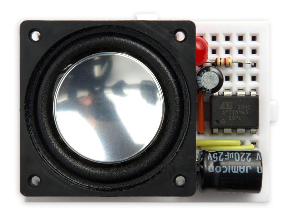
Tiny MIDI Player plays a MIDI tune from memory on an ATtiny85.
The notes sound like a music box or harpsichord, with a decaying envelope, and there are four channels, so up to four notes can play simultaneously. My demonstration program plays the Bach Fugue in D Minor; here's what it sounds like: midiplayer.mp3.
You can easily program it to play any MIDI music-box tune you like, from a site such as Music Box Maniacs, and you could use it as the basis for an electronic greeting card, a musical marriage proposal ring box, an electronic doorbell, or any other music-based project.
Introduction
This project started when I discovered Music Box Maniacs, a site that provides tunes you can print out as a paper strip for use with a range of mechanical music boxes. The tunes are also downloadable as MIDI files, and I thought it would be fun to write a program to convert the MIDI format to the format of binary numbers needed by my earlier Digital Music Box [Updated] project. Using a description of the MIDI file format [1] I wrote a converter program (in Lisp), but then realised that I could cut out the intermediate step by making a version of my music box project that would read a MIDI file directly from the microcontroller's flash memory. This would also have the advantage that it would remove the 32-note range limit of my original program, which encoded the tune as bit positions in 32-bit numbers.
My MIDI converter handles a subset of the MIDI format suitable for playing the music-box tunes on the Music Box Maniacs site, and I've tested it with several tunes from the site. However, I'm not sure how it will cope with a general MIDI file.
The circuit
The circuit is the same as my earlier Music Box, with the addition of an Error LED to give you feedback if an error occurs in parsing the MIDI code. The number of times the LED flashes tells you where in the MIDI format the error occurred.
The PWM output is fed straight to an 8Ω loudspeaker via an electrolytic capacitor to remove the DC. The inductance of the loudspeaker filters out the high-frequency components of the waveform:
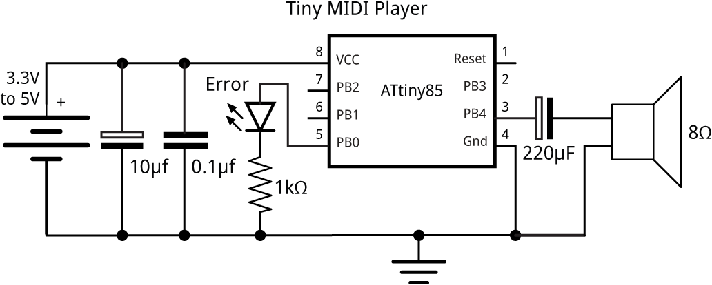
Circuit for the Tiny MIDI Player, based on an ATtiny85.
The 10µF capacitor across the supply line enables the ATtiny85 to cope with the current spikes caused by the music.
For a greeting card you might want to use a thin speaker, available from Sparkfun [2] or HobbyTronics in the UK [3].
If you want to feed the output to an audio amplifier you must include a low-pass filter, otherwise you risk overloading the amplifier. See Waveform Generation using an ATtiny85 for a suitable circuit.
Listing the MIDI data
The MIDI data of the tune you want to play is simply included at the start of the program; here's an example, abbreviated:
const uint8_t Tune[] PROGMEM = {
  0x4d, 0x54, 0x68, 0x64, 0x00, 0x00, 0x00, 0x06, 0x00, 0x01, 0x00, 0x01,
  0x03, 0xc0, 0x4d, 0x54, 0x72, 0x6b, 0x00, 0x00, 0x0a, 0x7e, 0x00, 0xff,
  ...
  0x50, 0xb0, 0x5b, 0x00, 0x00, 0xff, 0x2f, 0x00
};
Here's the procedure I used to list a MIDI file in the correct format.
- Copy the MIDI file into your home directory.
- Open the Terminal application.
- Type the following command, substituting the name of your MIDI file:
xxd -i musicbox.mid
The -i parameter tells xxd to output the data in C include format. The output will look something like:
unsigned char musicbox_mid[] = {
  0x4d, 0x54, 0x68, 0x64, 0x00, 0x00, 0x00, 0x06, 0x00, 0x01, 0x00, 0x01,
  0x03, 0xc0, 0x4d, 0x54, 0x72, 0x6b, 0x00, 0x00, 0x0a, 0x7e, 0x00, 0xff,
  ...
  0x50, 0xb0, 0x5b, 0x00, 0x00, 0xff, 0x2f, 0x00
};
unsigned int musicbox_mid_len = 2708;
The last line shows you the length of the data; this should be less than about 6000 for the MIDI data to fit in the available flash memory space.
- Cut and paste the data lines from your Terminal window to replace the corresponding lines in the Tiny MIDI Player source file.
Setup
The music box uses both of the ATtiny85 timers, and the watchdog timer. These are configured in setup().
First the 64MHz Phase-Locked Loop (PLL) is used the clock source for Timer/Counter1:
PLLCSR = 1<<PCKE | 1<<PLLE;
Then Timer/Counter1 is set up in PWM mode, to make it act as an analogue-to-digital converter, using the value in OCR1B to vary the duty cycle.
  TIMSK = 0;                     // Timer interrupts OFF
  TCCR1 = 1<<CS10;               // 1:1 prescale
  GTCCR = 1<<PWM1B | 2<<COM1B0;  // PWM B, clear on match
  OCR1B = 128;
  DDRB = 1<<DDB4;                // Enable PWM output on pin 4
The frequency of the square wave is specified by OCR1C; we leave it at its default value, 255, which divides the 64MHz clock by 256, giving a 250kHz square wave. This is high enough above our sampling rate to avoid anti-aliasing problems.
Timer/Counter0 is set up to generate an interrupt to output the samples:
  TCCR0A = 3<<WGM00;             // Fast PWM
  TCCR0B = 1<<WGM02 | 2<<CS00;   // 1/8 prescale
  OCR0A = 19;                    // Divide by 20
  TIMSK = 1<<OCIE0A;             // Enable compare match, disable overflow
The rate of this interrupt is the 16MHz system clock divided by a prescaler of 8, and a value in OCR0A of 19+1, giving 100kHz. This interrupt is used to output the four channels in turn, multiplexed, so the sample rate of each channel is 25kHz. I increased this from the 20kHz rate I used for my earlier Digital Music Box to give slightly higher quality. The interrupt calls an Interrupt Service Routine ISR(TIMER0_COMPA_vect) which calculates and outputs the samples.
Finally the Watchdog timer is configured to give an interrupt every 16ms, which is used to time the note output:
WDTCR = 1<<WDIE | 0<<WDP0; // Interrupt every 16ms
Generating the waveforms
The MIDI player uses DDS (Direct Digital Synthesis) to generate the waveforms. To give this project a music box sound I wanted to give the waveforms decaying envelopes. The ATtiny85 doesn't provide a hardware multiply, so to avoid the need for a multiply the basic waveform is a rectangle wave, so we only need to multiply the amplitude of the envelope by 1 or -1. Also, I made the envelope a linear decay, so we can calculate the amplitude values simply by decrementing a counter.
For each channel there are three variables; Freq[], the current note value, Acc[], the phase accumulator, and Amp[], the envelope amplitude value. For each sample the Freq[] value is added to the phase accumulator, Acc[]. The top bit of Acc[] is used to generate the square wave for the channel. The larger the value of Freq[], the higher the frequency generated by the top bit. Finally, the waveform is multiplied by the envelope, Amp[]. The four channels are multiplexed together, and the result is output to the analogue output.
Interrupt service routine
The critical part of the program is the Timer/Counter0 interrupt service routine, which outputs the waveform samples to the analogue output, and this gets called at a rate of about 95kHz. For the current channel c it updates the frequency accumulator Acc[c] and amplitude Amp[c], and calculates the value of the current note. This is then output to the Timer/Counter1 compare register OCR1B to give an analogue value on pin 4:
ISR(TIMER0_COMPA_vect) {
  static uint8_t c;
  signed char Temp, Mask, Env, Note;
  Acc[c] = Acc[c] + Freq[c];
  Amp[c] = Amp[c] - (Amp[c] != 0);
  Temp = Acc[c] >> 8;
  Temp = Temp & Temp<<1;
  Mask = Temp >> 7;
  Env = Amp[c] >> Volume;
  Note = (Env ^ Mask) + (Mask & 1);
  OCR1B = Note + 128;
  c = (c + 1) & 3;
}
Explaining this code line by line:
Acc[c] = Acc[c] + Freq[c];
Adds the frequency value for the current channel Freq[c] to the frequency accumulator, Acc[c]. The larger the value of Freq[c] the faster Acc[c] will change.
Amp[c] = Amp[c] - (Amp[c] != 0);
Decrements the amplitude value for the channel. The (Amp[c] != 0) part ensures that once it reaches zero it stays zero.
Temp = Acc[c] >> 8;
Sets Temp to the top 8 bits of the frequency accumulator.
Temp = Temp & Temp<<1;
This line sets the top bit to 1 if the top two bits are 1, and to 0 otherwise, which will give a rectangle wave with a 25/75 mark-space ratio. My original Digital Music Box used a square wave; for this project I decided to use a rectangle wave which has richer harmonics, and a nicer sound.
Mask = Temp >> 7;
Because Temp and Mask are signed values this smears the top bit down throughout the byte. If the top bit was 0 we get 0x00, and if 1 we get 0xFF.
Env = Amp[c] >> Volume;
By default Volume is 8 which sets Env to the top byte of the amplitude.
Note = (Env ^ Mask) + (Mask & 1);
Finally, bringing it all together. If Mask is 0x00 this sets Note to the Env value. If Mask is 0xFF this sets Note to the complement of Env + 1, or minus the Env value. Thus Note now contains a waveform that varies between plus and minus the current amplitude.
OCR1B = Note + 128;
The output register is set to Note+128 to give an unsigned 8-bit value.
c = (c + 1) & 3;
The four channels get output on successive interrupts, multiplexing the channels at the output.
Generating the scale
The well-tempered scale is generated by the constants in the array Scale[]:
unsigned int Scale[] = {
10973, 11626, 12317, 13050, 13826, 14648, 15519, 16442, 17419, 18455, 19552, 20715};
The first number, 10973, corresponds to C0. To get C4, middle C, which is four octaves higher, we divide this by 24 to get 686. The top bit of Acc[c] will therefore change with a frequency of 25000/(65536/685) or 261.7 Hz, middle C.
Changing the sound
Two variables let you change the sound of the notes. You can vary Volume between 7 and 9 to experiment with different volume settings. You can vary Decay between 14 and 12 to vary the envelope; 14 gives a long decay, and 12 gives the shortest decay. Values outside these ranges probably won't do anything useful.
The MINI interpreter
The MIDI interpreter reads the subset of MIDI needed to play a tune on the music box synthesiser. It assumes there is only one MIDI channel, and reads the tempo and division (ticks per beat) settings, but ignores most other settings.
Reading data
The MIDI interpreter uses the following routines to read the MIDI data:
readIgnore() skips over a specified number of bytes in the file:
void readIgnore (int n) {
  Ptr = Ptr + n;
}
readNumber() reads a number with a specified number of bytes precision up to 4:
unsigned long readNumber (int n) {
  long result = 0;
  for (int i=0; i<n; i++) result = (result<<8) + pgm_read_byte(&Tune[Ptr++]);
  return result;
}
readVariable() reads a number in the MIDI variable-precision format. This can consist of from one to four bytes:
unsigned long readVariable () {
  long result = 0;
  uint8_t b;
  do {
    b = pgm_read_byte(&Tune[Ptr++]);
    result = (result<<7) + (b & 0x7F);
  } while (b & 0x80);
  return result;
}
Each byte contributes seven bits to the result; if the top bit is set it indicates that another byte follows.
Playing a note
The interpreter calls noteOn() to play a note on the next available channel of the music box:
void noteOn (uint8_t number) {
  uint8_t octave = number/12;
  uint8_t note = number%12;
  unsigned int freq = Scale[note];
  uint8_t shift = 9-octave;
  Freq[Chan] = freq>>shift;
  Amp[Chan] = 1<<Decay;
  Chan = (Chan + 1) & 3;
}
Playing the MIDI data
Finally, here's the main routine to play the MIDI data. the variable Ptr is a pointer to the next byte to be read:
void playMidiData () {
  Ptr = 0;                                  // Begin at start of file
The first block in a MIDI file is the header, which specifies the number of tracks, and the division:
  // Read header chunk
  unsigned long type = readNumber(4);
  if (type != MThd) error(1);
  unsigned long len = readNumber(4);
  unsigned int format = readNumber(2);
  unsigned int tracks = readNumber(2);
  unsigned int division = readNumber(2);    // Ticks per beat
  TempoDivisor = (long)division*16000/Tempo;
The division is the number of subdivisions in a beat; typically 960. We then read the specified number of track blocks:
  // Read track chunks
  for (int t=0; t<tracks; t++) {
    type = readNumber(4);
    if (type != MTrk) error(2);
    len = readNumber(4);
    EndBlock = Ptr + len;
We then read successive events up to the end of each track block:
    // Parse track
    while (Ptr < EndBlock) {
      unsigned long delta = readVariable();
      uint8_t event = readNumber(1);
      uint8_t eventType = event & 0xF0;
      if (delta > 0) Delay(delta/TempoDivisor);
Each event specifies delta, the delay in time divisions before the event should take effect. For simultaneous events delta is zero.
Meta events have the event type 0xFF:
      // Meta event
      if (event == 0xFF) {
        uint8_t mtype = readNumber(1);
        uint8_t mlen = readNumber(1);
        // Tempo
        if (mtype == 0x51) {
          Tempo = readNumber(mlen);
          TempoDivisor = (long)division*16000/Tempo;
        // Ignore other meta events
        } else readIgnore(mlen);
The only one of these we are interested in is the Tempo meta event, which specifies the duration of a beat in microseconds. By default this is 500000; ie half a second, corresponding to 120bpm.
The remaining events are MIDI Events, identified by the first hexadecimal digit in their event type. The only one of these we are interested in is 0x90, Note On, which plays a note on the next available music box channel:
      // Note off - ignored
      } else if (eventType == 0x80) {
        uint8_t number = readNumber(1);
        uint8_t velocity = readNumber(1);
      // Note on
      } else if (eventType == 0x90) {
        uint8_t number = readNumber(1);
        uint8_t velocity = readNumber(1);
        noteOn(number);
      // Polyphonic key pressure
      } else if (eventType == 0xA0) readIgnore(2);
      // Controller change
      else if (eventType == 0xB0) readIgnore(2);
      // Program change
      else if (eventType == 0xC0) readIgnore(1);
      // Channel key pressure
      else if (eventType == 0xD0) readIgnore(1);
      // Pitch bend
      else if (eventType == 0xD0) readIgnore(2);
      else error(3);
    }
  }
}
I currently ignore the velocity value, because it's not applicable to a music box, but you could use this to set the initial amplitude of the note.
We have to identify the other MIDI events to allow us to skip them, because their length varies. Finally, anything else signals an error on the error LED.
Compiling the program
To be capable of supporting four channels the ATtiny85 needs to be run with a 16MHz clock; fortunately it provides a 16MHz clock option, without the need for a crystal, using the internal PLL to boost the internal 8MHz clock to 16MHz.
I compiled the program using Spence Konde's ATTiny Core [4]. Choose the ATtiny25/45/85 option under the ATtinyCore heading on the Board menu. Then choose Timer 1 Clock: CPU, B.O.D. Disabled, ATtiny85, 16 MHz (PLL) from the subsequent menus. Choose Burn Bootloader to set the fuses appropriately. Then upload the program using ISP (in-system programming); I used Sparkfun's Tiny AVR Programmer Board; see ATtiny-Based Beginner's Kit.
Here's the whole Tiny MIDI Player program, including the data for the Bach Fugue in D Minor [5] that I used in the prototype: Tiny MIDI Player Program.
- ^ The MIDI File Format on NTU CSIE.
- ^ Thin Speaker on Sparkfun.
- ^ Thin Speaker on HobbyTronics.
- ^ ATTinyCore on GitHub.
- ^ Bach Fugue in D Minor on Music Box Maniacs.
blog comments powered by Disqus