Magic 3D Clock
27th June 2019
This clock displays the time as an autostereogram on a colour TFT display. The time is invisible until you view it with your eyes focussed in the distance, when the time will jump out in 3D, appearing as four digits:
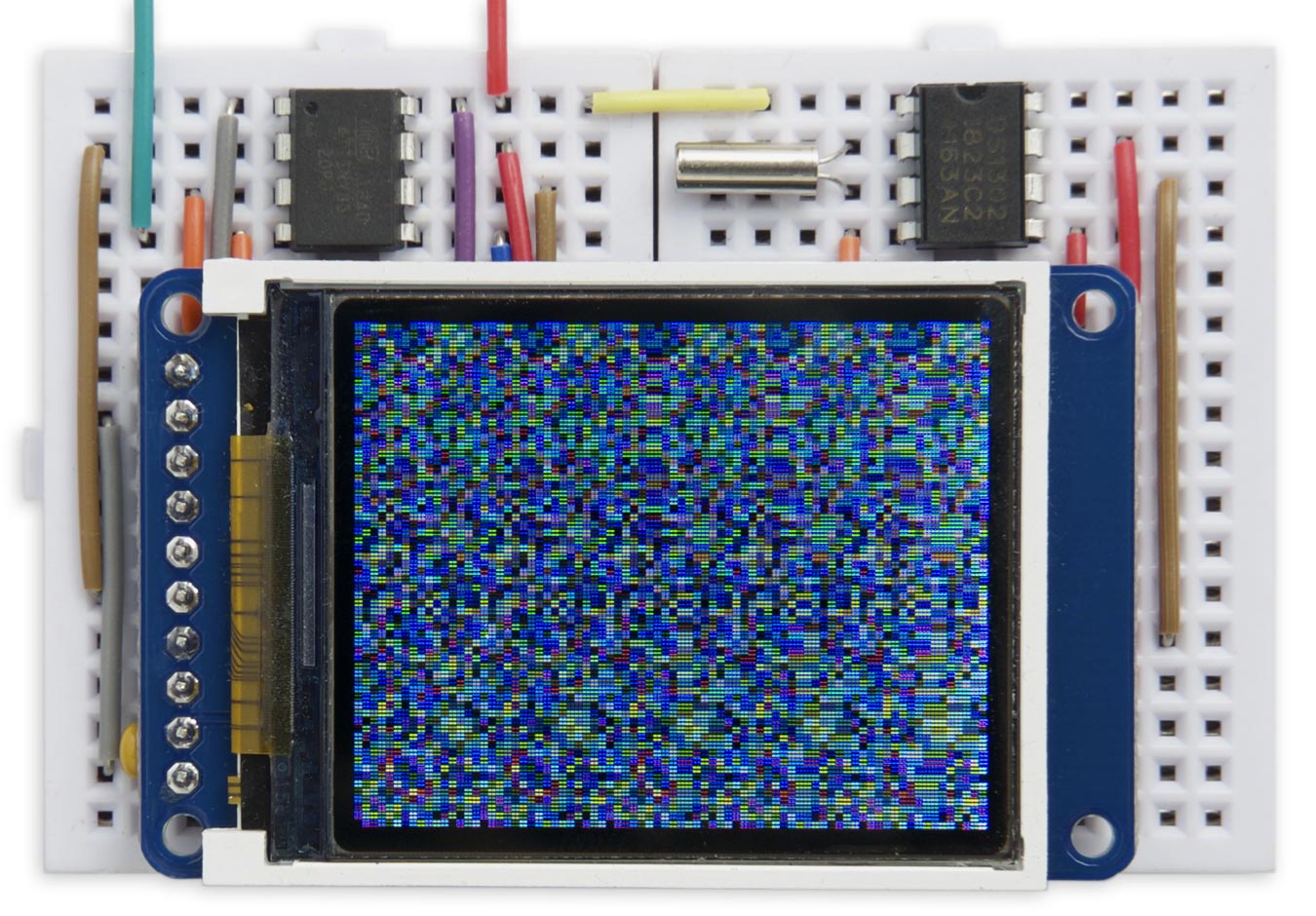
Magic 3D Clock displays the time as an autostereogram. It's 12:45.
It uses an ATtiny85 driving a TFT 160x128 colour display, and the timekeeping is done by a DS1302 RTC chip.
Introduction
This isn't perhaps the most convenient way of seeing the time, but it's a fun demonstration of autostereograms, made popular by the Magic Eye books of the 1990s. It's ideal if you don't want to be constantly reminded of the time, but want to be able to check it when you need it.
To view the clock you need to focus on a point behind the clock until the random dots snap together to create a new image, with the time shown in 3D.
The background
The fact that we've got two eyes is what enables us to deduce how far away things are. For example, if you're viewing a bush in front of a hedge we know that the bush is nearer than the hedge because the image of the bush is shifted relative to the hedge in one eye compared to the other. If you viewed the scene with just one eye you'd see a texture of leaves that gave no information about distance.
Autostereograms take advantage of the brain's ability to process the images from both eyes to generate depth information, using computer-generated images. To understand how autostereograms work we first need to start from stereoscopic photographs.
Stereoscopic photographs
A stereoscopic photograph is a pair of photographs, taken from slightly different camera positions corresponding to the distance between the eyes. When viewed with the eyes slightly diverged, or through a viewer, the brain combines the images to create the illusion of a 3D image. It became a craze in Victorian times [1], and more recently several cameras have been marketed to allow you to take and view sterescopic pictures.
Random-dot stereograms
The next development was the random-dot stereogram, discovered in 1919 [2]. This is a pair of identical random-dot fields; in one of the pair a shape has been shifted left or right. The shape is invisible until you merge the images, as with a stereoscopic photograph; the shape then stands out in 3D. This effect was influential in helping understand how the brain processes depth information in visual images.
Autostereograms
This brings us to the autostereogram, in which a single random dot image can be created which, when viewed correctly, reveals a hidden 3D image.
It works by dividing the random dot image into vertical bands. When viewed with the eyes slightly diverged, or focussed behind the image, the left eye views bands 1 to 4 and the right eye bands 2 to 5:
How an autostereogram works by dividing an image into vertical stripes.
If each vertical stripe was the same, the eyes would see identical images and there would be no depth perception. However, by shifting a feature horizontally between two adjacent stripes we can make one eye see it shifted horizontally relative to the other eye, making it appear at a different depth.
Viewing autostereograms
Note that it may take a few attempts to see autostereograms for the first time, so don't give up if you can't immediately see them. It helps to relax and let your eyes go slightly out of focus while staring at the image; slowly the 3D hidden image will appear to pop out. There are some sample autostereograms later in this article which you can experiment with.
The circuit
Here's the circuit of the Magic 3D Clock:
Circuit of the Magic 3D Clock, based on an ATtiny85 and DS1302 RTC.
Graphics display
For the display I used a 1.8" 160x128 colour TFT graphics display, available from Adafruit [3] or The Pi Hut in the UK [4]. It's based on an ST7735S display controller [5]. Alternatively, similar displays are available from AliExpress [6].
Real-Time Clock
There aren't enough pins left on the ATtiny85 to run it with a crystal, so I decided to use an external RTC chip. I chose the DS1302 [7] because it's low-cost, and available in a PDIP package which fits conveniently in the breadboard. Although it requires 3 pins to interface to it, it can share the SCK and I/O pins with the display, so all we need is a separate chip-select pin.
Although I haven't implemented it here, the DS1302 supports a backup battery, or supercapacitor with automatic trickle-charging, which is useful for preserving the time if you have to change the main clock battery.
How it works
The following images demonstrate how the Magic 3D Clock works by combining a coloured texture with a height map. They were generated directly from the image data.
Texture
The coloured texture is the background pattern that will be merged by the eyes to create the 3D image. The choice of pattern determines how easy it is to focus on the texture, and so see the hidden image. If it's too fine, like randomly-coloured pixels, it's difficult to latch on to features in the image, but if it's too coarse, like large coloured squares, there isn't enough detail to represent the hidden image exactly. I found that 2x2 randomly coloured squares were a good compromise.
Here's what my random texture looks like without any hidden image:
Height map
The height map is a greyscale image where the grey level represents the height of the object to be drawn in 3D. Black in the greyscale corresponds to the background, at height 0, and white corresponds to the closest part of the object.
For example, here's a test image I used of a circle on a sloping floor; in fact the floor is stepped because of the limited resolution of the display:

And here's the autostereogram created by merging the height map with the random texture in the previous image:
Clock display
For the clock I used a very simple height map with just one height level for the digits:
The numerals were drawn using a 12x14 pixel character set, scaled up by a factor of four to fit the four digits neatly in a square.
Here's an autostereogram showing the time using the above heightmap:
The program
The display
The routines to draw to the 160x128 TFT display are from my earlier article: Tiny TFT Graphics Library.
Texture and height maps
The texture and height map routines are called for each of the pixels on the display, specified by its x and y coordinates.
First, the random colour texture is defined by the function Texture(). It returns a colour for the pixel at coordinates (x, y):
colour_t Texture (int x, int y) {
  int cx = x & 0xFFFE;
  int cy = y & 0xFFFE;
  return Rand(cx*cx + cy*cy + cx*cy);
}
It calls a simple random-number generator, Rand():
colour_t Rand (int s) {
  return (s * 48271) & 0xFFFF;
}
This is designed to return the same random number when it's called with the same argument.
The height map specifying the digits in the current time is drawn by the routine FourDigits(). It returns a boolean value for the pixel at coordinates (x, y) depending on whether the pixel should be white or black:
boolean FourDigits (int x, int y, unsigned int time) {
  int xs = x - 44;
  int ys = y - 4;
  if ((ys < 0) || (55 < ys && ys < 64) || (ys > 119)
  || (xs < 0) || ((47 < xs) && (xs < 56)) || (xs > 103)) return 0;

  if (xs > 55) xs = xs - 8;
  if (ys > 63) ys = ys - 8;

  int xc = xs / 48;
  int yc = ys / 56;
  int d = (2 * (1 - yc)) + xc;
  char c = time>>(12-4*d) & 0x0F;
  return Pixel((xs % 48) / 4, (ys % 56) / 4, c);
}
The ten digits and colon character are 12x14 pixel bitmaps defined by an array CharMap[11][14] stored in program memory. The routine Pixel() returns the colour of a specified pixel in the character bitmap for a given digit:
boolean Pixel (int x, int y, char c) {
  return (pgm_read_word(&CharMap[c][13-y]))>>(11-x) & 1;
}
Magic clock display
Finally, the complete Magic 3D Clock display is generated by the function Magic(). This calculates each row in the image as a series of five slices, each of which is 32 pixels wide. The first slice is set to the appropriate values in the texture. Each subsequent slice is a copy of the previous slice, with pixels shifted right by two pixels where the corresponding pixels in the height map are white:
void Magic (unsigned int time) {
  // Build row
  for (int y=0; y<128; y++) {
    for (int x=0; x<32; x++) Row[x] = Texture(x, y);
    for (int slice=0; slice<4; slice++) {
      for (int k=0; k<32; k++) {
        int x = (k + ((slice + 1) * 32));
        Row[x] = Row[x - 32 + 2 * FourDigits(x, y, time)];
      }
    }
    for (int x=0; x<160; x++) {
      fore = Row[x];
      PlotPoint(x, y);
    }
  }
}
RTC interface
The interface to the RTC chip consists of the two routines Send(), to write a byte to the clock chip, and Read(), to read a byte from the clock chip. These are called by SetTime(), which sets the current time, and GetTime(), which reads the current time. Both work with the hours and minutes in binary-coded decimal (BCD). Finally GetSecs() reads the number of seconds in BCD.
I've provided a function PlotTime() that you can use to check that the RTC is working; it simply displays the time on the display as six digits in the format HH:MM:SS. To use it replace loop() with:
void loop () {
  PlotTime();
}
Compiling the program
I compiled the program using Spence Konde's ATTiny Core [8]. Choose the ATtiny25/45/85 option under the ATTinyCore heading on the Board menu. Then check that the subsequent options are set as follows (ignore any other options):
Chip: "ATtiny85"
Clock: "8 MHz (internal)"
B.O.D: "B.O.D. Disabled"
Timer 1 Clock: "CPU"
By default the ATtiny85 runs at 1MHz. Choose Burn Bootloader to set the fuses for 8MHz operation.
Change the value of TimeNow at the start of the program to the current time, then upload the program using ISP (in-system programming) using a programmer such as Sparkfun's Tiny AVR Programmer Board [9].
Here's the Magic 3D Clock program: Magic 3D Clock Program.
Further suggestions
In the 3D time display you could have the four digits at different heights, by drawing them in the height map with different grey levels.
I also thought about making a 3D analogue clock face by drawing a circle and two hands.
- ^ Introduction to the The London Stereoscopic Company on londonstereo.com.
- ^ Random dot stereogram on Wikipedia.
- ^ 1.8" Color TFT LCD display on Adafruit.
- ^ Adafruit 1.8" Color TFT LCD display on The Pi Hut.
- ^ ST7735 datasheet on Display Future.
- ^ 1.8 inch TFT LCD Module 128x160 on AliExpress.
- ^ DS1302 Datasheet on Maxim Integrated.
- ^ ATTinyCore on GitHub.
- ^ Tiny AVR Programmer on SparkFun.
blog comments powered by Disqus