Bounce-Free Rotary Encoder
28th October 2017
This article describes a simple routine to interface a rotary encoder to a microprocessor; I've chosen the ATtiny85 because it's the simplest processor you could use for such an application. The main routine that does all the work is just 11 lines of C, but I've also written a demonstration program that displays the encoder value on a serial 7-segment display, and the direction of rotation on an LED:
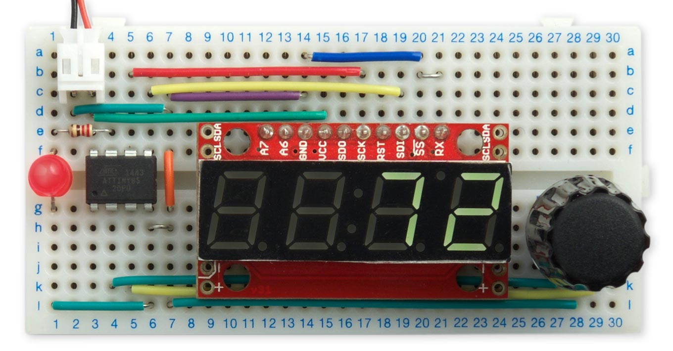
Test circuit to display the count from a rotary encoder on a seven-segment display.
I've also included an example program showing how to use the routine on an Arduino Uno.
Introduction
Rotary encoders let you control an analogue value by rotating a knob. They generate a series of digital pulses reflecting the distance you've turned the knob, and you can also determine the direction it has been turned.
I used the following sample rotary encoders to test the program:
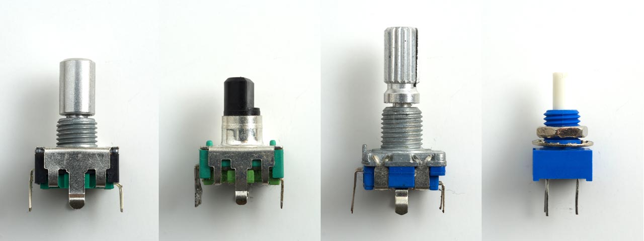
Here's the specification of these encoders (left to right):
| Pulses per rotation | Detents | Switch | |
| Adafruit rotary encoder [1] | 48 | 24 | Yes |
| Sparkfun rotary encoder [2] | 24 | 12 | Yes |
| EC11 rotary encoder [3] | 40 | 20 | Yes |
| Bourns rotary encoder [4] | 32 | No | No |
Some of the rotary encoders have click positions, or detents. The routine described here gives two pulses per click position, so you may prefer to divide the count by two if you are using one of these encoders.
My favourite rotary encoder is the one from Bourns. It has a very smooth but precise action, with no detents, and Bourns makes matching potentiometers in an identical housing.
It's quite hard to find knobs that fit some of these encoders. In particular, the Sparkfun encoder has a very short shaft, so many knobs will be too deep. The Bourns Rotary Encoder has a 3.2mm shaft diameter, which is smaller than the usual 0.25" shaft. This is not a problem with the Adafruit rotary encoder, which includes a matching knob.
How they work
Rotary encoders work by providing two switches that are activated in sequence when you rotate the knob. They are usually called A and B, and there's a third common terminal C that is typically connected to ground. By checking the state of both switches your program can tell both how far the knob has been rotated, and in which direction.
The signals produced by each switch can be represented by the following familiar diagram:
However, what actually happens is something closer to this:
At each changeover the switches generate an unpredictable amount of contact bounce, which is unavoidable because of the mechanical construction of the switch contacts. Clearly, simply counting the transitions is going to give an incorrect count.
The objective
A rotary encoder interface should satisfy the following requirements:
- Rotating the encoder through a given angle, such as one turn, should produce the same change in value.
- The change in value should be the same whether you turn the encoder slowly, or spin it as quickly as possible.
- Turning the knob through several turns, and then back to its original position, should return the value to its exact starting value.
These requirements are all really equivalent, and depend on eliminating the effect of contact-bounce in the switches.
Eliminating the effects of contact bounce
One solution is to add extra hardware, such as a low-pass filter or a monostable, to eliminate the contact bounce. Fortunately there's a simpler way, which can be implemented with a bit of simple software:
A pin-change interrupt is set up on input A so an Interrupt Service Routine is called on each transition. This routine copies the state of B into a new variable C. Since B is stable during the contact bounce on A, the same value will get copied on each transition:
This gives us in C a cleaned-up version of A, free from any contact bounce.
At each transition we then compare the state of the cleaned-up signal C with its previous state. If it has changed, a transition has occurred in C, and we count it as a valid count.
The program
To set up the rotary encoder interface we need to set input pullups on the encoder inputs A and B, and set a pin-change interrupt on A:
  pinMode(EncoderA, INPUT_PULLUP);
  pinMode(EncoderB, INPUT_PULLUP);
  PCMSK = 1<<EncoderA;        // Configure pin change interrupt on A
  GIMSK = 1<<PCIE;            // Enable interrupt
  GIFR = 1<<PCIF;             // Clear interrupt flag
Then here's the implementation of the Interrupt Service Routine. Variables a and b hold the current states of the two inputs, the global variable a0 holds the previous state of a, and c0 holds the cleaned-up signal:
ISR (PCINT0_vect) {
  int a = PINB>>EncoderA & 1;
  int b = PINB>>EncoderB & 1;
  if (a != a0) {              // A changed
    a0 = a;
    if (b != c0) {
      c0 = b;
      ChangeValue(a == b);
    }
  }
}
When a valid count is detected the routine calls ChangeValue() with a boolean parameter to indicate the direction of the count.
Circuit
Here's the circuit of the demo rotary encoder interface. It displays the direction on an LED and the count on a serial seven-segment display module; I chose this because it's easy to interface to the ATtiny85 using just two SPI lines, clock and data:
Demo rotary encoder interface displays the direction on an LED and the count on a seven-segment display.
Compiling the program
I compiled the program using Spence Konde's ATTiny Core [5]. Choose the ATtiny25/45/85 option under the ATtinyCore heading on the Board menu. Then choose Timer 1 Clock: CPU, B.O.D. Disabled, ATtiny85, 1 MHz (internal) from the subsequent menus; this is the default fuse setting on a new ATTiny85. Then choose Upload to upload the program using ISP (in-system programming); I used the Sparkfun Tiny AVR Programmer [6].
Here's the whole Bounce-Free Rotary Encoder program: Bounce-Free Rotary Encoder Program.
Arduino Uno
Here's an example showing how to use the routine on the Arduino Uno: Bounce Free Rotary Encoder Uno
- ^ Rotary encoder + extras on Adafruit.
- ^ Rotary encoder on Sparkfun.
- ^ EC11 Rotary Encoder Audio Digital Potentiometer on Aliexpress.
- ^ 3315Y-001-016L - Incremental Rotary Encoder on Farnell.
- ^ ATTinyCore on GitHub.
- ^ Tiny AVR Programmer on Sparkfun.
blog comments powered by Disqus