Using the Arduino IDE Without Cores
9th February 2016
This article shows how to set up the Arduino IDE so you can use it to program Arduino boards and ATmega or ATtiny chips without the overhead of the core Arduino functions, and gives alternatives to the most common core functions.
Introduction
The Arduino IDE provides a simple user interface for compiling and downloading programs to Arduino boards and stand-alone AVR chips. Although it's less fully featured than the official Atmel product, Atmel Studio [1], it's less daunting for beginners to use, and more importantly for me, it works on the Mac which isn't currently supported by Atmel Studio.
In addition to providing a programming environment, the Arduino IDE provides a core set of functions, called the "core", designed to make programming the Arduino Uno and other Arduino boards easier for beginners, removing the need to refer directly to the processor's registers, timer/counters, and other modules [2]. Cores have also been written for many other members of the ATmega and ATtiny series, so you can use most of the same functions with these chips too; see Choosing a Friendly AVR Chip.
However as I've become more familiar with the datasheets of the chips I'm using I've found advantages in accessing their registers directly, rather than using the Arduino core functions.
The main advantages of not using the core functions are:
- You avoid the time and memory overhead imposed by many of the core functions, so your code can run faster and use less RAM and program memory.
- Your code is fully portable to other development systems, such as Atmel Studio.
- You can program AVR chips for which no Arduino core is available; all you need to do is provide an appropriate section in the boards.txt file.
Programming the Arduino Uno without cores
Here's the procedure for setting up the Arduino IDE so it doesn't use the core functions. This was tested with versions 1.0.5 and 1.6.8 of the Arduino IDE on a Mac; the procedure on a PC, or with different versions of the IDE, may be slightly different:
Edit the boards.txt file
- Ctrl-click on the Arduino.app icon and choose Show Package Contents from the context menu.
- In the Finder window type boards.txt in the search box:
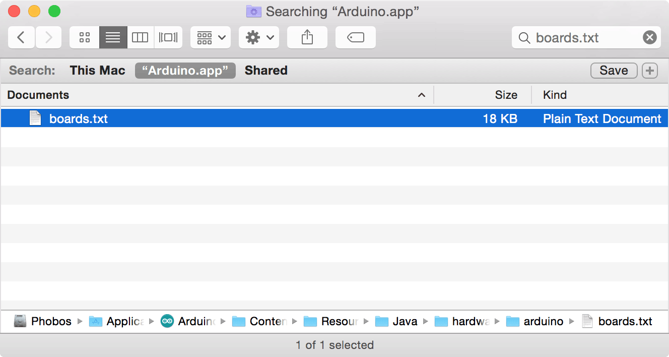
- Ctrl-click on the boards.txt file and choose Show in Enclosing Folder from the context menu.
You should see the contents of the arduino folder (IDE version 1.0.5) or the avr folder (IDE version 1.6.8):
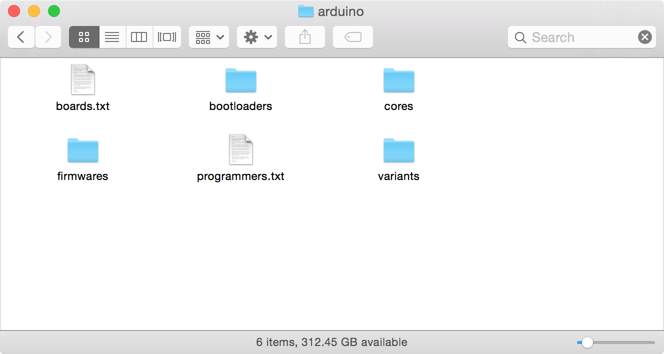
- Double-click the boards.txt file to edit it.
- In the section starting uno.name=Arduino Uno (IDE 1.0.5) or uno.name=Arduino/Genuino Uno (IDE 1.6.8) change:
uno.build.core=arduino
to
uno.build.core=empty
- Save the file.
Note that if you prefer not to change the existing Arduino Uno section you could create a copy of the settings with a different prefix, such as unoempty, and a different name, such as Arduino Uno Empty, and make the change to that. Then select Arduino Uno Empty from the Boards menu.
Add an empty core
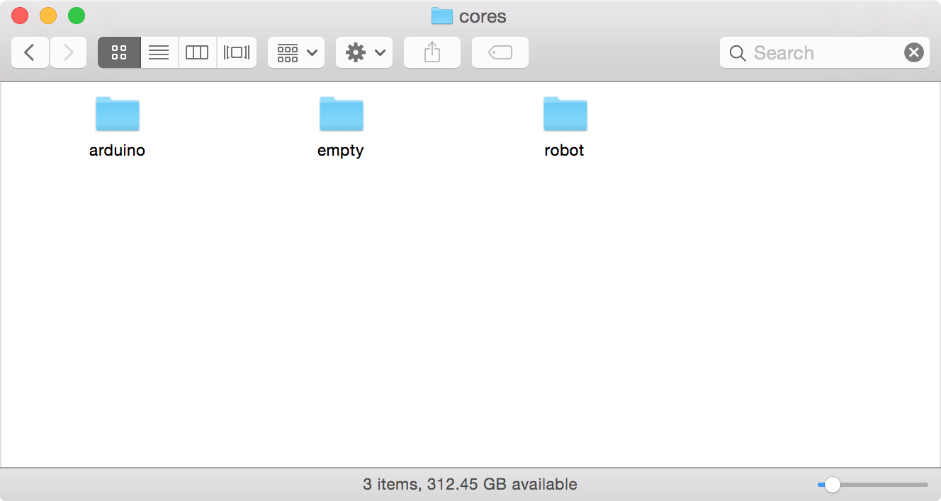
- Now double-click the cores folder to show the cores. There should be arduino and robot folders.
- Download and expand the following archive: empty.zip
- Put the resulting folder called empty in the cores folder:
You should now be able to compile and run the Blink sketch in the following section.
Arduino Uno Blink sketch for the empty core
Here's the Blink sketch for the empty core we have created:
/* Arduino Uno Blink sketch for use with the empty core */

#include <avr/io.h>
#include <stdint.h>

int led = 5; // In port B

void setup() {
 DDRB = DDRB | 1<<led;         // Define PB5 as an output
}

volatile long Counter;

void delay (long n) {          // Delay by n milliseconds
 Counter = 469 * n;
  do Counter--; while (Counter != 0);
}

// The loop routine runs over and over again forever:
void loop() {
  PORTB = PORTB | 1<<led;      // Take PB5 high
  delay(1000);                 // Wait for a second
  PORTB = PORTB & ~(1<<led);   // Take PB5 low
  delay(1000);                 // Wait for a second
}

// We need main()
int main() {
  setup();
  for(;;) loop();
}
Like the original Blink sketch supplied with the Arduino IDE this should flash the LED connected to pin 13 on the Arduino Uno.
The different parts of this are explained in the section Alternatives to core functions below.
Programming ATtiny chips without cores
To program ATtiny chips without using the core functions, edit the boards.txt file in the Arduino-Tiny [3] or ATTinyCore [4] core you are using, and change the line such as:
attiny85at1.build.core=tiny
to:
attiny85at1.build.core=empty
You don't need to add the empty core folder because the tiny or attiny cores already include one.
Alternatives to core functions
includes
When using the empty core you need to add these includes at the start of your program to include the AVR register definitions and standard C++ routines:
#include <avr/io.h>
#include <stdint.h>
setup and loop
Arduino programs are normally written with the initialization in setup() and the main program in loop(), rather than the standard int main() function required by C++. You therefore need to include the following definition at the end of your program:
int main() {
  setup();
  for(;;) loop();
}
pinMode
To program an I/O pin you first need to check which register and bit number it corresponds to. For example, Arduino pin 13 is equivalent to PB5.
To configure a pin as an output or input you set or clear the corresponding bit in the appropriate DDRx register (DDB5 is a constant defined as 5, the pin number):
DDRB = DDRB | 1<<DDB5; // pinMode(13, OUTPUT)
DDRB = DDRB & ~(1<<DDB5); // pinMode(13, INPUT)
To set an input pullup you first define the pin as an input, and then write a '1' to the corresponding bit in the PORTx output register (PORTB5 is a constant defined as 5, the pin number):
DDRB = DDRB & ~(1<<DDB5);
PORTB = PORTB | 1<<PORTB5;     // pinMode(13, INPUT_PULLUP)
digitalWrite
To write to an I/O pin you set or clear the corresponding bit in the appropriate PORTx register:
PORTB = PORTB | 1<<PORTB5; // digitalWrite(13, HIGH)
PORTB = PORTB & ~(1<<PORTB5); // digitalWrite(13, LOW)
digitalRead
To read an I/O pin you read the corresponding bit in the appropriate PINx register:
temp = PINB & ~(1<<PORTB5); // temp = digitalRead(13)
analogWrite
To use an I/O pin for analogue output you first need to configure the appropriate Timer/Counter into PWM mode for that pin in setup(). For example, Arduino pin 9 corresponds to OC1A in Timer/Counter1, which allows up to 10-bit PWM. We can set it up in this mode as follows:
 TCCR1A = 2<<COM1A0 | 3<<WGM10; // 10-bit PWM non-inverting mode
 TCCR1B = 1<<WGM12 | 3<<CS10;   // Divide clock by 64 = 250kHz
 DDRB = DDRB | 1<<DDB1;         // pinMode(9, OUTPUT)
To write an analogue value we then need to write the value to the appropriate output compare register, OCR1A:
OCR1A = 1000; // analogWrite(9, 1000)
This will set pin 9 to 1000/1024 * 5V, or 4.88V.
analogRead
To use an I/O pin for analogue input you first need to configure the Analogue-to-Digital Converter in setup(). For example, the Arduino pin A0 corresponds to ADC0. We can set this up as follows:
ADMUX = 1<<REFS0 | 0<<MUX0;    // Vcc as ref, ADC0 (PC0)
ADCSRA = 1<<ADEN | 7<<ADPS0;   // Enable ADC, 125kHz clock
To read an analogue value from the pin we then need to start a conversion, and when the conversion is ready read the ADC register:
ADCSRA = ADCSRA | 1<<ADSC;     // Start
do ; while (ADCSRA & 1<<ADSC); // Wait while conversion in progress
int result = ADC;              // analogRead(A0)
delay
For a simple substitute for delay() you can use a loop adjusted to give roughly the right timing:
volatile long Counter;

void delay (long n) {         // Delay by n milliseconds
  Counter = 469 * n;
  do Counter--; while (Counter != 0);
}
Note that Counter must be defined as volatile or the compiler will optimise it out of the loop, eliminating the delay.
For more accurate delays, and to implement timers like millis(), you need to set up a Timer/Counter as a timer, or use the Watchdog Timer.
Updates
25th February 2016: By default interrupts are off after reset, but the Arduino core enables them. If you're compiling a program that uses interrupts you will need to add the following statement somewhere in setup():
sei();
Also, you should add the following includes at the start of your program to provide the routines for interrupts and PROGMEM:
#include <avr/interrupt.h>
#include <avr/pgmspace.h>
23rd April 2016: I have now tested this on IDE version 1.6.8 and updated the instructions slightly to describe the differences.
- ^ Atmel Studio on the Atmel site.
- ^ Language Reference on the Arduino site.
- ^ Arduino-Tiny core on Google Code.
- ^ ATTinyCore on GitHub.
blog comments powered by Disqus