Tiny Time Watch
3rd December 2016
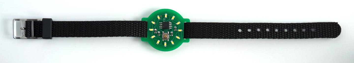
Here is my design for a minimalist ATtiny85-based watch using 12 LEDs, arranged like a clock face, to show the time analogue-style:
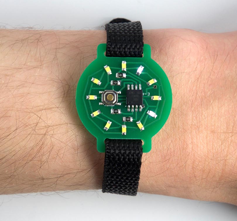
The ATtiny85-based Time Time watch; it's five past four.
To show the time you press the button on the watch face, and the time is then displayed for four seconds. It lights one LED to show the hour, and flashes another LED to show the minutes to the nearest five minutes, like the hour and minute hands on a clock. If only one LED lights up you know that both hands are pointing to the same hour mark.
The Tiny Time watch uses the ATtiny85's built-in oscillator, fine-tuned to get it as accurate as possible, and my watch keeps time to within a couple of minutes over 24 hours. You can adjust the time by holding down the button for more than four seconds.
It's powered by a CR2032 button cell, and I've used several techniques to reduce the current consumption, so the battery should last for over a month. The total component cost, excluding the PCB, is about £5/$5, and it's straightforward to build.
For an improved version of this project see Tiny Time 2 Watch.
Introduction
I was inspired to design this watch after reading about Sam DeRose's Nerd Watch [1] which takes minimalism one step further. It seems fortuitous that you can drive 12 LEDs from four I/O lines using charlieplexing, exactly the number you need to display a clock face, taking advantage of the fact that you can drive two LEDs from every different pair of the I/O lines. One more I/O line is needed to detect the button press, neatly using the five I/O lines available on the ATtiny85.
Construction
Here's the circuit of the Tiny Time watch, laid out like the circuit board:
Circuit of the ATtiny85-based Time Time watch.
I built the watch on a small printed circuit board, using SMD components, with all the components apart from the battery holder soldered to one side of the board. I used an SOIC ATtiny85 and 0805 resistors and LEDs, so they are relatively easy to solder by hand. I arranged the LEDs to avoid tracks crossing in the layout which explains the rather haphazard order, but this is easily accommodated in the software. The following table shows which LED lights up when you take one I/O line high and the other I/O line low:
The button is a miniature SMD pushbutton available from Sparkfun [2], available from Proto-PIC in the UK [3], and the battery holder is an SMD 20mm coin cell holder also available from Sparkfun [4], or from Proto-PIC in the UK [5].
The LEDs are 0805 size, and I chose white LEDs as they tend to be the brightest. I got mine from Bright Components in the UK, who sell them for under £1 for ten [6]. The LEDs should be soldered with the same orientation, with the negative sides facing the centre of the board.
I designed the board in Eagle and as an experiment sent it to both Seeed Fusion [7] and OSH Park [8] for fabrication. Here's the preview from the OSH Park service:
There's a link to the Eagle files at the end of the article if you want to make yourself a board. Alternatively, because the track layout avoids vias you could use a single-sided board, milled using a milling machine such as the Othermill [9]; you could then glue the battery holder to the other side, and connect it through two holes to the main circuit.
I used a Youyue 858D+ hot air gun at 250°C to solder the SMD components onto the front of the board, and then finally soldered the battery holder onto the back of the board using a conventional soldering iron. If you don't have a hot air gun you should be able to solder the SMD components with a bit of care using a fine-tipped soldering iron.
I found a suitable 12mm wide thread-through watch strap from a German supplier [10]:
The program
This section explains the various sections of the Tiny Time Watch program.
The display
The 12 LEDs are driven by the four I/O lines PB0, PB1, PB3, and PB4. PB2 is used for the pushbutton, because it is assigned to the interrupt INT0, which makes detecting the button a bit easier.
The array Pin[5][5] specifies how the LEDs are connected to the five I/O lines:
int Pins[5][5] = {{-1, 10, -1,  2,  0 },
                  {11, -1, -1,  3,  7 },
                  {-1, -1, -1, -1, -1 },
                  { 1,  9, -1, -1,  5 },
                  { 6,  8, -1,  4, -1 } };
The first row of the array specifies which LEDs have their cathodes connected to PB0: the LED at 10 o'clock has its anode connected to PB1, the LED at 2 o'clock has its anode connected to PB3, and the LED at 12 o'clock has its anode connected to PB4. The values in the array corresponding to PB2 are set to -1.
I used Timer/Counter0 running at 250 Hz both to count the number of seconds, and to multiplex the display. This is set up in setup() as follows:
  TCCR0A = 2<<WGM00;            // CTC mode; count up to OCR0A
  TCCR0B = 0<<WGM02 | 2<<CS00;  // Divide by 8 = 62500Hz
  OCR0A = 249;                  // Divide by 250 -> 250Hz
  TIMSK = TIMSK | 1<<OCIE0A;    // Enable compare match interrupt
Here's the interrupt service routine:
ISR(TIM0_COMPA_vect) {
  Ticks++;
  if (Ticks == Tickspersec) {Ticks = 0; Secs++; }
  if (!DisplayOn) return;
  DisplayNextRow();
  Timeout--;
  if (Timeout != 0) return;
  if (PINB & 1<<PINB2) {
  // If button is now up, turn off display
    DDRB = 0;                     // Blank display - all inputs
    PORTB = 0xFF;                 // All pullups on
    DisplayOn = false;
  } else {
  // If button is still down, set time
    Timeout = Tickspersec/2;        // Half second delay
    Secs = (unsigned long)(Secs + 300);
    Fivemins = (unsigned long)((Secs+299)/300)%12;
    Hours = (unsigned long)((Secs+1799)/3600)%12;
  }
}
First it increments the seconds counter, Secs, every 250 calls.
Then, if the display has been turned on, it calls DisplayNextRow() to display the next row of LEDs.
Finally, it counts down the variable Timeout to blank the display automatically four seconds after the button has been pressed.
If the button is held down for more than four seconds the time starts advancing 5 minutes every half second, to allow you to set the correct time, until you release the button.
Display multiplexing
The routine DisplayNextRow() works as follows:
void DisplayNextRow() {
  Cycle++;
  byte row = Cycle & 0x03;
  if (row > 1) row++;    // Skip PB2
  byte bits = 0;
  for (int i=0; i<5; i++) {
    if (Hours == Pins[row][i]) bits = bits | 1<<i;
    if ((Cycle & 0x20) && (Fivemins == Pins[row][i])) bits = bits | 1<<i;
  }
  DDRB = 1<<row | bits;
  PORTB = bits | 0x04;         // Keep PB2 high
}
Up to two LEDs can be lit at once. The LED specified by the variable Hours is used to show the hours, and is displayed continuously. The LED specified by the variable Fivemins is used for the minutes, and flashes every 32 times the routine is called.
The bottom two bits of the variable Cycle determine which row is being displayed. For a given row the array Pins[row][i] is checked to see if any of the LEDs in that row need to be displayed or flashed. If so, the appropriate bits are set in the variable bits. This is then written to the port.
Displaying the time
The pushbutton is connected to the INT0 interrupt input, which generates an interrupt to display the time. It is set up in setup() as follows:
  PORTB = 0xFF;                 // All pullups on
  MCUCR = MCUCR | 2<<ISC00;     // Interrupt on falling edge
  GIMSK = 1<<INT0;              // Enable INT0 interrupt
The interrupt service routine resets the variable Timeout, to keep the display on, and calculates the values of the variables Hours and Fivemins:
ISR(INT0_vect) {
  // Turn on display
  Timeout = Tickspersec*4;              // Display for 4 secs
  DisplayOn = true;
  Fivemins = (unsigned long)((Secs+299)/300)%12;
  Hours = (unsigned long)((Secs+1799)/3600)%12;
  Step = 0;
}
The two corrections +299 and +1799 need some explanation:
I decided that since the watch only shows you the time to within five minutes, it should round up the time to the next five minute mark, so you are early rather than late for appointments! The correction +299 in the calculation of Fivemins achieves this.
My first version of the watch program displayed the hour number as a continuously illuminated light and the five minute mark as a flashing light, but for times after half past the hour this gave a confusing display. For example, for 2:50 the watch would light the 2 and 10 LEDs, but one's instinct is to read this as ten to two; ie 1:50. The current version therefore displays times later than half past the hour by lighting the next hour number, which gives a more familiar display. This is implemented with the correction +1799 in the calculation of Hours.
Reducing the current consumption
I was keen to make the watch last as long as possible on a single battery. Because the internal oscillator is used to keep the time it's not possible to save power by putting the processor to sleep, and the watchdog timer isn't accurate enough for timekeeping. I therefore investigated other ways of saving power.
The current consumption from 5V without any of these power savings was 1.68 mA. These are the techniques I used, with the power saving in brackets after each:
Disable the ADC (0.32 mA)
Since we aren't using the ADC I disabled it with the line:
ADCSRA &= ~(1<<ADEN);
Switch off the clocks to the USI, ADC, and Timer/Counter 1 (0.20 mA)
As described in the ATtiny85 datasheet, you can save power by switching off the clocks to the circuits you're not using by setting bits in the Power Reduction register, PRR:
PRR = 1<<PRUSI | 1<<PRADC | 1<<PRTIM1; // Turn off clocks
Switch to Idle mode between interrupts (0.70 mA)
Between interrupts we can switch the processor to idle mode, which halts the processor clock but leaves the timers and interrupt system running:
set_sleep_mode(SLEEP_MODE_IDLE);
...
sleep_enable();
sleep_cpu();
Reduce the system clock speed from 1MHz to 0.5MHz (0.10 mA)
Finally, we can reduce the system clock to 0.5MHz to further reduce the current consumption:
CLKPR = 1<<CLKPCE;
CLKPR = 4<<CLKPS0;
If you inadvertently reduce the system clock below 500kHz you will not be able to reprogram the chip using ISP (In-System Programming), because the processor isn't running fast enough to execute the instructions to clear the flash memory. I therefore included a 5 second delay before reducing the clock speed; if ISP fails, reset the processor and try again within 5 seconds, and it should then work.
The final current consumption is about 0.36mA at 5V, dropping to 0.23mA at 3V. A typical CR2032 battery has a capacity of 225mAH, so it should last over a month.
Compiling the program
I compiled the program using Spence Konde's excellent new ATTiny Core, which now supports all the ATtiny processors and supersedes the various earlier ATtiny cores [11]. Select the ATtinyx5 series option under the ATtiny Universal heading on the Boards menu. Then choose Timer 1 Clock: CPU, B.O.D. Disabled, ATtiny85, 1 MHz (internal) from the subsequent menus. This is the default fuse setting on new ATtiny85s; otherwise choose Burn Bootloader to set the fuses appropriately.
I uploaded the program using a clip that fitted to the top of the SMD ATtiny85 [12], using Sparkfun's AVR Pocket Programmer [13]. The advantage of this over the Tiny AVR Programmer Board that I usually use is that it allows you to program a circuit while it's powered by its own supply, so I don't have to remove the button cell from the Tiny Time watch.
Calibrating the internal oscillator
To avoid the need for a crystal, and the two additional I/O pins that would need, the watch uses the ATtiny85 internal oscillator for its timekeeping. The internal oscillator isn't as accurate as a crystal, but I included the ability to fine-tune it, to get the watch as accurate as possible.
I decided to calibrate the clock by adjusting the Timer/Counter0 compare match value, OCR0A, rather than using the built-in OSCCAL register for calibration. The OCR0A value allows us to adjust the calibration by about 0.25%, whereas the OSCCAL calibration is about 1%. Also, the OCR0A calibration is linear, so after measuring the error you can calculate what the value should be. I used the following procedure:
- Power the watch from a CR2032 battery, as the oscillator is affected by the supply voltage.
- Run the following program to generate a frequency on the PB0 pin.
- Measure the frequency with a frequency meter, and recompile the test program with different values of OCR0A.
- Adjust the value until you get the frequency as close as possible to 1000Hz.
- Copy the OCR0A value to the setup() routine in the Tiny Time Watch program.
Here's the program:
// Calibrate clock
void setup() {
  delay(5000);
  CLKPR = 1<<CLKPCE;
  CLKPR = 4<<CLKPS0;            // Clock to .5 MHz

  // Set up signal on PB0
  TCCR0A = 1<<COM0A0 | 2<<WGM00;// Toggle PB0
  TCCR0B = 0<<WGM02 | 1<<CS00;  // Divide by 1
  OCR0A = 249;                  // Divide by 250
  pinMode(0, OUTPUT);           // Adjust for 1000 Hz on PB0
}

void loop() {
}
I found it took me just a few minutes to get the frequency within better than 1Hz of 1000Hz.
If you don't have a frequency meter you could run the watch for a few hours, and then from the time error calculate the adjustment you need to make.
Here's the whole Tiny Time Watch program: Tiny Time Watch Program.
Alternatively, get it on GitHub here together with the Eagle files for the PCB: Tiny Time Watch on GitHub.
- ^ The Nerd Watch on the Other Machine Co. website.
- ^ Mini Pushbutton Switch - SMD on SparkFun.
- ^ Mini Push Button Switch (SMD) on Proto-PIC.
- ^ Coin Cell Battery Holder - 20mm (SMD) on SparkFun.
- ^ Coin Cell Battery Holder - 20mm (SMD) on Proto-PIC.
- ^ 10x White 0805 Surface Mount (SMD/SMT) LED on Bright Components.
- ^ Seeed Fusion PCB service.
- ^ OSH Park PCB service.
- ^ Othermill Pro on Other Machine Co.
- ^ Watch strap 12mm black nylon/textile one-piece strap on Watchbandcenter.com.
- ^ ATTinyCore on GitHub.
- ^ IC test Clip - SOIC 8-pin on SparkFun.
- ^ Pocket AVR Programmer on Sparkfun.
blog comments powered by Disqus