ATtiny85 Sound Level Meter
1st January 2016
My first project this year is a simple digital sound level meter consisting of an ATtiny85, an LED bargraph display, and an electret microphone:
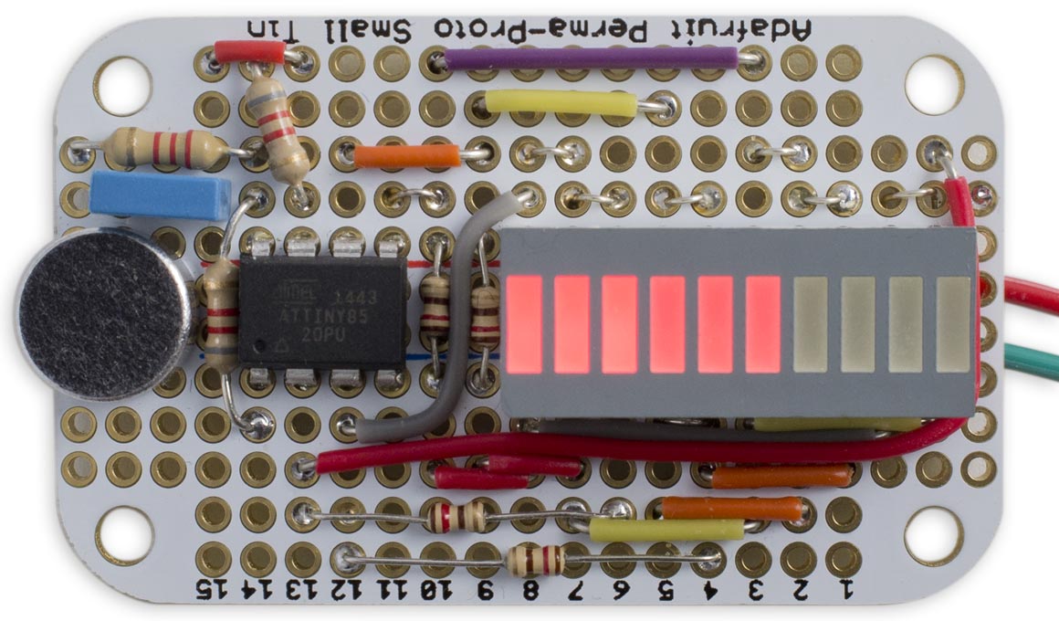
ATtiny85 Sound Level Meter, displays the input from an electret microphone on a bargraph display.
It's sensitive enough to respond to speech, and shows just how much functionality you can get out of the tiny 8-pin ATtiny85 processor. The ATtiny85 not only drives the 10-bar LED display directly, but it also receives the direct input from an electret microphone, amplifies and digitises it, and converts it to a logarithmic value before displaying it.
The project could be used as a display for your sound system, or as a sound-sensitive pendant. You could also use it to monitor the sound level in your environment. The front end on its own could form the basis for a voice-activated switch; for example, to turn on a light with a vocal command.
The bargraph display is based on my previous article ATtiny85 Bargraph Voltmeter.
Components
For the display I used a low-cost red 10-LED bargraph display, available from Sparkfun [1], or HobbyTronics in the UK [2]. Alternatively you could use up to 12 discrete LEDs.
For the microphone I used an electret microphone module, available from Adafruit [3] or from Pimoroni in the UK [4]. This gives an output of a few mV for speech, up to a few hundred mV for loud music.
After prototyping the circuit on a mini breadboard I built it on one of Adafruit's Perma-Proto Small Tin prototyping boards [5].
Analogue to digital conversion
The sound level meter measures the output from the electret microphone using one of the analogue-to-digital converters built in to the ATtiny85. The standard single-ended analogue conversion mode gives a maximum sensitivity of 1.1V for a reading of 1024, using the internal 1.1V voltage reference, but this isn't quite sensitive enough for an electret microphone. The usual approach is to add an op-amp to boost the output of the microphone up to the 1.1V needed for the analogue input [6].
However, the ATtiny85 provides a x20 gain option, corresponding to a full-scale sensitivity of 55mV, which is ideal for this application. However, there's a catch; the x20 gain is only available in the differential analogue conversion modes, which require two analogue inputs, and we don't have another I/O line available. Fortunately there's a solution; we can configure the Reset line as ADC0, and keep this close to Vcc so it doesn't cause a reset; we can then choose a x20 differential conversion mode using ADC0 and ADC1.
The ADC is configured in setup() for differential conversion using ADC0 (PB5) and ADC1 (PB2) with a x20 gain. The ADC is driven by a clock which is divided down from the system clock; the datasheet recommends an ADC clock of between 50kHz and 200kHz, so I chose a prescaler of 8 which gives a frequency of 125kHz:
  ADMUX = 2<<REFS0 | 0<<REFS2 | 11<<MUX0; // Internal 1.1V ref, ADC0 vs ADC1 x20
  ADCSRA = 1<<ADEN | 3<<ADPS0;            // Enable, 125kHz ADC clock
The display is multiplexed using Timer/Counter0, and the ADC is read using the routine ReadADC() which is called from the main display loop, while the display is blanked, to minimise noise. For more information about the display routine see ATtiny85 Bargraph Voltmeter.
Logarithmic conversion
The ADC measures the voltage output from the electret microphone, but sound levels are usually displayed in decibels, a logarithmic measure, because each doubling of voltage output corresponds to equal increases in loudness. To convert the 10-bit binary ADC value to an approximate logarithmic value from 0 to 10 we simply count the bit-width of the value, excluding leading zeros. Here are a couple of examples:
-
1023 is 0b1111111111 which has a bit-width of 10, so log21023 = 10.
- 9 is 0b1001 which has a bit-width of 4, so log29 = 4.
We then display the logarithmic value as the corresponding number of bars on the display. Fortunately there's an efficient way to combine both of these operations into a single calculation, implemented by the routine LogBar():
int LogBar (unsigned int x) {
  x = x | x>>1;
  x = x | x>>2;
  x = x | x>>4;
  x = x | x>>8;
  return x;
}
LogBar() effectively smears the leftmost '1' bit across the rest of the binary value, filling in all the zeros with ones.
Circuit
Here's the complete circuit of the sound level meter:
Circuit of the Sound Level Meter, based on an ATtiny85.
The value of the two 10kΩ resistors marked 0.1% is not critical, but they should be matched to 0.1% or better, to minimise the voltage offset between the two differential analogue inputs. I had a pack of ten 5% tolerance 8.2kΩ resistors, and chose the two with the closest values using a digital multimeter. If you don't get them matched closely enough there will be a constant display, even with no input signal. If you can't find two values that are close enough you may be able to correct for a small constant offset in the program.
The circuit draws about 1.3mA when there's no input.
Compiling the program
I compiled the program using the Arduino-Tiny core extension to the Arduino IDE [7]. Select the ATtiny85 @ 1 MHz (internal oscillator; BOD disabled) option on the Boards menu. This is the default fuse setting on new ATtiny85s; otherwise choose Burn Bootloader to set the fuses appropriately. Then upload the program to the ATtiny85 using the Tiny AVR Programmer Board; see ATtiny-Based Beginner's Kit.
Here's the whole ATtiny85 Sound Level Meter program: Sound Level Meter Program.
Update
25th November 2021: Corrected the polarity of the electrolytic coupling capacitor on the circuit diagram.
- ^ 10 Segment LED Bar Graph - Red on SparkFun.
- ^ 10 Bar Red DIL LED Display on HobbyTronics.
- ^ Electret Microphone - 20Hz-20kHz Omnidirectional on Adafruit.
- ^ Electret Microphone - 20Hz-20kHz Omnidirectional on Pimoroni.
- ^ Adafruit Perma-Proto Small Mint Tin Size Breadboard PCB on Adafruit.
- ^ Electret Microphone Amplifier - MAX9814 with Auto Gain Control on Adafruit.
- ^ Arduino-Tiny core on Google Code.
blog comments powered by Disqus