CAN Bus Monitor
30th August 2023
This is a simple CAN Bus monitor that displays information about the packets on a CAN Bus:
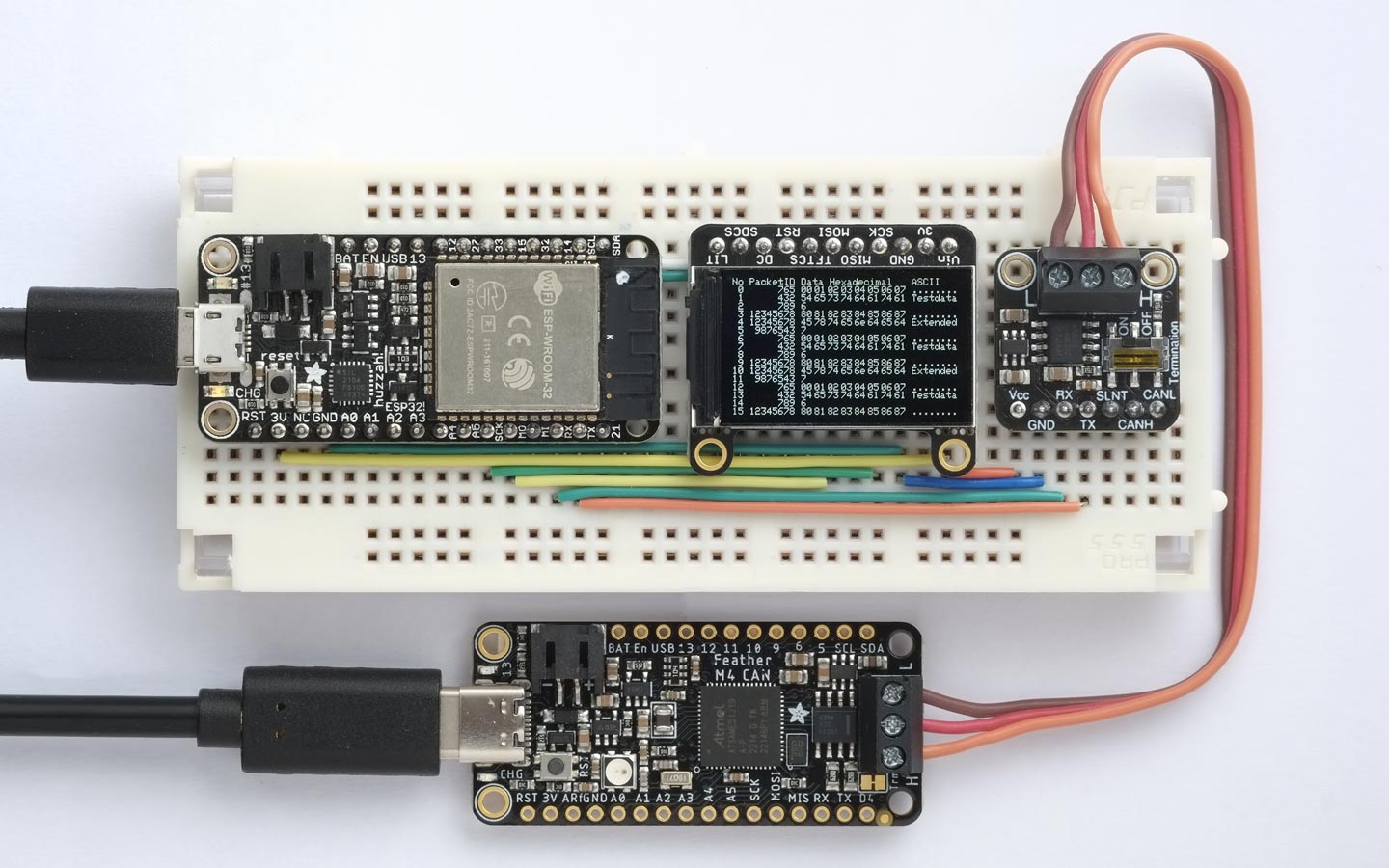
The CAN Bus Monitor displays a list of the packets on the CAN Bus.
It's based on an Adafruit ESP32 Feather, a CAN Bus Transceiver, and a 240x135 TFT Display.
I tested it by sending packets from an Adafruit Feather M4 CAN Express board, based on an ATSAME51.
Introduction
CAN (Controller Area Network) Bus is a communications interface widely used in the automotive industry. It was developed by Bosch and is now ISO approved. Like I2C it uses two wires and ground, but it uses differential signals enabling it to communicate reliably at a faster data rate over longer distances, typically up to 1000 meters with suitable cabling.
Although CAN Bus was originally developed for use in vehicle electronics, it's also ideal for use in wider applications such as home automation, model railways, and plant irrigation. I've recently been experimenting with it, and designed this monitor to help me debug the packets being sent over the bus.
CAN Bus cabling
The CAN bus consists of two signal lines: CAN High (CAN-H) and CAN Low (CAN-L), with an additional common GND line. Each end of the bus should be terminated with 120Ω resistors to reduce signal reflections, and most transceivers include switched termination for this purpose. The cabling is typically a twisted pair for CAN-H and CAN-L, plus a third GND cable. Shielding is optional, but if provided, only one end should be connected to GND. The speed of the bus can be 1 Mbps for lengths of up to 40 metres, or up to 1000 metres at the lower speed of 50 kbps.
CAN Bus support
Support for CAN Bus is being included in an increasing number of microcontrollers and microcontroller boards, such as the ESP32 family, and the recently released Arduino Uno R4 Minima and WiFi boards. Note that although these boards include support for the CAN Bus protocol, they need the addition of an external transceiver to connect to the CAN Bus line. Adafruit have also released the Feather M4 CAN board which is based on the ATSAME51, and it includes a transceiver on the board.
The differential signal used by CAN Bus requires a voltage swing of 5V, so if you are using the transceiver with a 3.3V microcontroller you will need to provide an additional 5V supply. This isn't usually a problem on boards powered by USB, because they provide a 5V power output. Alternative you could use a voltage doubler to generate the 5V from 3.3V.
A popular transceiver is the TJA1051 [1], available on a breakout board from Adafruit [2].; this board includes a charge-pump voltage doubler to generate the 5V supply from a 3.3V supply.
If you want to provide CAN Bus to a board that doesn't already support it you can use an interface chip such as the MCP2515 or MCP25625, which convert between SPI and CAN Bus. One such board is the Arduino MKR CAN Shield [3]. With the MCP2515 you need to add a separate transceiver, but the MCP25625 includes a built-in transceiver.
The CAN Bus monitor
The CAN Bus monitor reads each packet on the bus and displays it on a colour TFT 240x135 display. For each packet the following information is displayed:
- No: The packet number since monitoring started, displayed in decimal.
- PacketID: The packet ID; an 11-bit identifier for standard packets, or a 29-bit identifier for extended packets, displayed in hexadecimal.
- Data Hexadecimal: Up to eight bytes of data, displayed in hexadecimal.
- Data ASCII: The same data shown in ASCII.
For some applications, and when debugging, it's convenient to provide the packet data in ASCII, so the CAN Bus Monitor shows the packet data both in hexadecimal and in the equivalent ASCII characters. If there's no valid ASCII character a dot is shown.
A special type of packet, called a Remote Transmission Request (RTR), is used to request data from another device on the bus. This contains a Data Length Code (DLC) but no data. These packets are displayed with the following information:
- No: The packet number since monitoring started, displayed in decimal.
- PacketID: The packet ID, as above.
- Data Hexadecimal: the Data Length Code (DLC).
The circuit
The circuit is based on three modules:
- An ESP32 board. I used an original Adafruit ESP32 Feather. The V2 that Adafruit are currently selling should work equally well [4], or any other ESP32 board.
- A 240x135 Colour TFT Display. I used the Adafruit 240x135 Colour TFT Display [5], but an alternative is available from several suppliers on AliExpress [6]
- A TJA1051 CAN Bus Transceiver breakout. I used the Adafruit CAN Bus Transceiver [7].
Interconnection diagram for the three modules in the CAN Bus Monitor.
Construction
I decided to build the project on a breadboard, but most commonly available breadboards are either 30 rows wide, which was too small, or 60 rows wide, which would leave a lot of unused space. After a lot of searching I was very pleased to find a 43-row breadboard [8], which is perfect for this project. I didn't want the row numbering screen printed on the breadboard, so I removed this using lighter fluid as a solvent.
The program
I wrote an initial version of the program in uLisp before converting it to C for the final version.
The program uses Sandeep Mistry's Arduino CAN library [9] which supports the ESP32. For details of the functions see CAN API.
The display needs the Adafruit GFX Library and the Adafruit ST7735 and ST7789 Library.
Setup
In setup() the program initialises the display and CAN Bus, and prints the information headings on the display:
void setup() {
  tft.init(135, 240);
  tft.setRotation(1);
  tft.fillScreen(ST77XX_BLACK);

  CAN.setPins(RX, TX);

  // Start the CAN bus at 500 kbps
  if (!CAN.begin(500000)) {
    tft.print("Starting CAN failed!");
    while (1);
  }

  tft.print("No PacketID Data Hexadecimal");
  tft.setCursor(15*6 + 7*14, 0);
  tft.println("ASCII");
}
On the ESP32 you can specify any pins to be used for the CAN Bus; I used the Serial pins RX and TX, and assigned them with the call:
CAN.setPins(RX, TX);
You can use different pins if you need RX and TX for another application.
Displaying a packet
Each packet is read in loop() by a call to CAN.parsePacket(), and then displayed by the subsequent statements:
void loop() {
  uint8_t packet[8];
  int packetsize = CAN.parsePacket();

  if (packetsize) {                                // Received a packet
    for (int i=0; i<8; i++) {
      if (CAN.available()) packet[i] = CAN.read(); else packet[i] = 0;
    }
    if (!CAN.packetRtr()) {                        // Not RTR; packet contains data
      tft.printf("%2d %8x", Line++, (uint32_t)CAN.packetId());
      for (int i=0; i<8; i++) {                    // Print data in hexadecimal
        tft.setCursor(12*6 + i*14, Line*8);
        if (i < packetsize) tft.printf("%02x", packet[i]); else tft.print("  ");
      }
      tft.print(' ');
      for (int i=0; i<8; i++) {                    // Print data in ASCII
        char c = packet[i];
        if (c >= 32) tft.print(c); else tft.print('.');
      }
    } else {                                       // RTR packet; show DLC
      tft.printf("%2d %8x %d", Line++, (uint32_t)CAN.packetId(), CAN.packetDlc());
    }
    tft.println();
  }
  if (Line == 16) for(;;);
}
With the default 6x8 pixel character set the display can show 16 lines of 34 characters. This isn't quite wide enough to display all the information I wanted to show, so I reduced the space between the data bytes to three pixels, rather than a full six-pixel space. This is achieved by calling tft.setCursor() to set the coordinates for printing subsequent characters.
After 16 packets have been received and displayed the program waits in a loop, and you can continue monitoring by pressing the ESP32's Reset button. Alternatively you could make the program clear the display and continue monitoring after a short delay.
Testing
I tested the CAN Bus Monitor using an Adafruit Feather M4 CAN Express [10] to generate packets, by running a test program based on their feather_m4can_tx example. It uses the Adafruit CAN Library [11], which is based on Sandeep Mistry's library.
The test program repeatedly sends two standard packets and a standard RTR packet, followed by two extended packets and an extended RTR packet.
Resources
Here's the CAN Bus Monitor program: CAN Bus Monitor program.
And here's the CAN Bus Sender: CAN Bus Sender.
Updates
5th September 2023: Replaced the photograph of the CAN Bus Monitor, because there was a glitch on the screen of the previous photograph.
- ^ TJA1051 datasheet on nxp.com.
- ^ Adafruit CAN Pal - CAN Bus Transceiver on Adafruit.
- ^ Arduino MKR CAN Shield on Arduino.cc.
- ^ Adafruit ESP32 Feather V2 on Adafruit.
- ^ Adafruit 1.14" 240x135 Color TFT Display on Adafruit.
- ^ 1.14in SPI 240x135 RGB TFT display on AliExpress.
- ^ Adafruit CAN Pal on Adafruit.
- ^ PJP 19100 Professional Prototyping Board on Rapid Online.
- ^ Arduino CAN library on GitHub.
- ^ Adafruit Feather M4 CAN Express on Adafruit.
- ^ Adafruit CAN Library on GitHub.
blog comments powered by Disqus