Secret Maze
1st February 2018
This simple game for the ATtiny85 is a maze that you navigate with four pushbuttons. The available paths in each direction are shown by four LEDs. A lit LED means that your way is blocked by a wall, and a speaker beeps if you try to move in that direction. When you get to the goal a tune confirms you've succeeded!
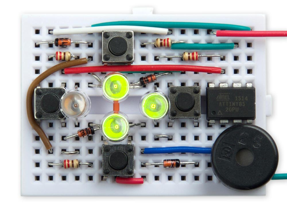
The Secret Maze game based on an ATtiny85; your only option is to move left.
The project is a good example of what you can achieve with the diminuitive ATtiny85; as well as mapping the maze it's driving four LEDs, reading four pushbuttons, and playing tones through a speaker!
For a printed circuit board for this project see Secret Maze PCB.
The maze
The maze is designed on a 16x16 grid, and is represented in the program as an array of 16-bit numbers, with a '1' bit representing a wall and a '0' bit representing a passageway.
Here's the definition of a simple smaller maze to show how this works:
const int Startx = 5, Starty = 5;
const int Goalx = 9, Goaly = 5;
unsigned int Maze[11] = {
  0b01111111111,
  0b01000000001,
  0b01011111101,
  0b01010000101,
  0b11010110101,
  0b10010010001,
  0b11010110101,
  0b01010000101,
  0b01011111101,
  0b01000000001,
  0b01111111111 };
The constants Startx and Starty define the coordinates of the starting position, and Goalx and Goaly the coordinates of the goal. The array Maze[] then defines the shape of the maze, with the origin at top right: in the binary numbers a '1' represents a wall and '0' a passageway. Here's a diagram of the maze defined above; the red circle is the start and the green circle is the goal:
The maze given in the program listing linked at the end of the article is larger (16 x 16) and much trickier. It's designed so you can't solve it using the trick of following the left-hand (or right-hand) wall, and it includes several traps to lure you into a loop. Even so, if you saw a printed representation of the maze it would be quite easy to solve visually, so to avoid revealing the maze I've given the definition in hexadecimal in the program.
Navigating the maze using the four-LED interface makes it challenging, and unless you've got a very good visual memory you'll probably need to draw a map on a piece of paper as you traverse it.
Interfacing to the LEDs and buttons
The ATtiny85 provides five I/O lines. One of these was needed for the piezo speaker, leaving four available to control four LEDs and read four pushbuttons.
The solution is to use charlieplexing, a method of driving LEDs that takes advantage of the fact that each I/O line can have one of three states: low, high, or high-impedance when defined as an input. All the I/O lines are defined as inputs when no LEDs are illuminated, and to light one LED you take one I/O line low and another I/O line high. The LED at the intersection of those two lines will then light up.
The simplest way to visualise this is to draw a diagram, where each cell shows a combination of one I/O line low and another I/O line high. You can place an LED in each cell. The grey squares show positions where you can't connect an LED, because an I/O line can't be both high and low at the same time:
So the total number of LEDs you can control with four I/O lines is 12.
Instead of an LED you can put a pushbutton in series with a diode into any cell (see Postscript). To test the state of the pushbutton you take one I/O line low, make the other I/O line an input with a pullup, and read its state. So you can control any combination of any mixture of 12 LEDs and pushbuttons.
In this application I only needed four LEDs and four pushbuttons; the arrangement I used is as shown here:
The circuit
Here's the circuit of the Secret Maze game:
Circuit of the Secret Maze game, based on an ATtiny85.
It's made a bit more complicated by the wiring needed for the charlieplexing.
The pushbuttons are 6mm square tactile buttons, available from SparkFun [1] or Proto-PIC in the UK [2]. The diodes are 1N4148 small-signal diodes, but almost any diodes should be suitable. For the LEDs I used 5mm clear green LEDs, but again any LEDs should be suitable. The speaker is a miniature piezo transducer.
I managed to squeeze all the components onto a mini breadboard; these are available from SparkFun [3] or HobbyTronics in the UK [4].
The program
Playing beeps
The program uses the routine note() to play a note to the piezo speaker on I/O pin 4. This is from my article Playing Notes on the ATtiny85.
Displaying the lights and checking the pushbuttons
The state of the lights is set by the bottom four bits in the global variable Lights, and the states of the pushbuttons by the corresponding bits in the global variable Buttons:
The lights and buttons are multiplexed by the Timer/Counter0 OCR0A compare match interrupt service routine. Timer/Counter0 is set up to give a 500Hz interrupt in setup():
  TCCR0A = 2<<WGM00;                     // CTC mode
  TCCR0B = 2<<CS00;                      // /8 prescaler
  OCR0A = 249;                           // 500 Hz interrupt
  TIMSK = TIMSK | 1<<OCIE0A;             // Enable interrupt
Each call to the interrupt service routine checks the button on one row, and lights the light on one row. First the following code tests a button and sets the appropriate bit in Buttons if it is down:
  int button = ((Row<<1) + 1) % 5;
  if (PINB & 1<<button) {
    Buttons = Buttons & ~(1<<Row);
  } else {
    Buttons = Buttons | 1<<Row;
  }
Then the following code checks the appropriate bit in Lights and lights the LED if it is a '1':
  button = ((Row<<1) + 1) % 5;             // Button
  int light = Row ^ 0x03;                  // LED
  if (Lights & 1<<Row) {
    DDRB = (DDRB & (1<<Output)) | 1<<Row | 1<<light;
    PORTB = 1<<light | 1<<button;
  } else {
    DDRB = (DDRB & (1<<Output)) | 1<<Row;
    PORTB = 1<<button;
  }
This routine takes care to avoid changing the Output bit, used for the speaker.
Reading the maze
The routine Bit() checks a cell in the maze at coordinates x,y and returns '1' if it's a wall:
int Bit (int x, int y) {
  return Maze[y]>>x & 1;
}
The routine Look() returns the state of the four cells around the cell x,y as the bottom four bits in the result, using the same order as the bits in Lights and Buttons:
int Look (int x, int y) {
  return Bit(x, y+1)<<3 | Bit(x+1, y)<<2 | Bit(x-1, y)<<1 | Bit(x, y-1);
}
Navigating the maze
The main program, in loop(), then runs the game. The position of the player in the maze is represented by X,Y which is initially set to the starting position:
int X = Startx, Y = Starty;
The program then repeats the following steps:
- Call Look() to display the current position on the lights.
- Wait until the keys have been released.
- Check whether we've reached the goal, and if so, play a tune.
- Check Buttons and wait for a keypress, including key debouncing.
- Set the variables dx and dy to the direction corresponding to the keypress.
- Check whether the move is valid, by calling Bit().
- If the destination is blocked call Beep() to play a tone. Otherwise update X and Y to make the move.
Compiling the program
I compiled the program using Spence Konde's ATTiny Core [5]. Choose the ATtiny25/45/85 option under the ATtinyCore heading on the Board menu. Then choose Timer 1 Clock: CPU, B.O.D. Disabled, ATtiny85, 1 MHz (internal) from the subsequent menus. If necessary choose Burn Bootloader to set the fuses appropriately. Then upload the program using ISP (in-system programming); I used Sparkfun's Tiny AVR Programmer Board; see ATtiny-Based Beginner's Kit.
Here's the whole Secret Maze program: Secret Maze Program.
Further suggestions
With a bit more programming you could make the game generate a new random maze automatically when you solved the previous one.
Another option would be to provide a breadcrumb-trail button that would allow you to drop breadcrumbs to help you see where you have already been in the maze. These would be indicated by a fifth LED.
To make the mazes harder you could allow some of the walls to be directional, so you could pass through one way, but not get back the other way. This could be achieved by using two bits, rather than one, to define each cell.
Postscript
Why are the diodes needed in series with each pushbutton? The answer is to protect against the user pressing two pushbuttons at once when an LED is illuminated. For example, consider the case when the LED between PB0 and PB3 is illuminated. PB0 is at 0V and PB3 is at VCC. Now suppose the user holds down the pushbutton between PB3 and PB1, and the pushbutton between PB1 and PB0. Without the diodes this would short between 0V to VCC.
Addendum
14th March 2018: The note routine in the first version of the program could sometimes leave the output to the piezo speaker at a high level, which caused a perceptible background buzzing from the speaker. I've updated the program to define the output to the speaker as an input when no note is being produced, which fixes this.
- ^ Mini Pushbutton Switch on SparkFun
- ^ Mini Push Button Switch (Pack of 10) on Proto-PIC.
- ^ Breadboard - Mini Modular on SparkFun.
- ^ Mini Breadboard on HobbyTronics.
- ^ ATTinyCore on GitHub.
blog comments powered by Disqus