Four Sample Player
21st January 2020
This is a simple audio player, based on an ATtiny85, that plays one of four audio samples from a DataFlash chip at the press of one of four buttons:
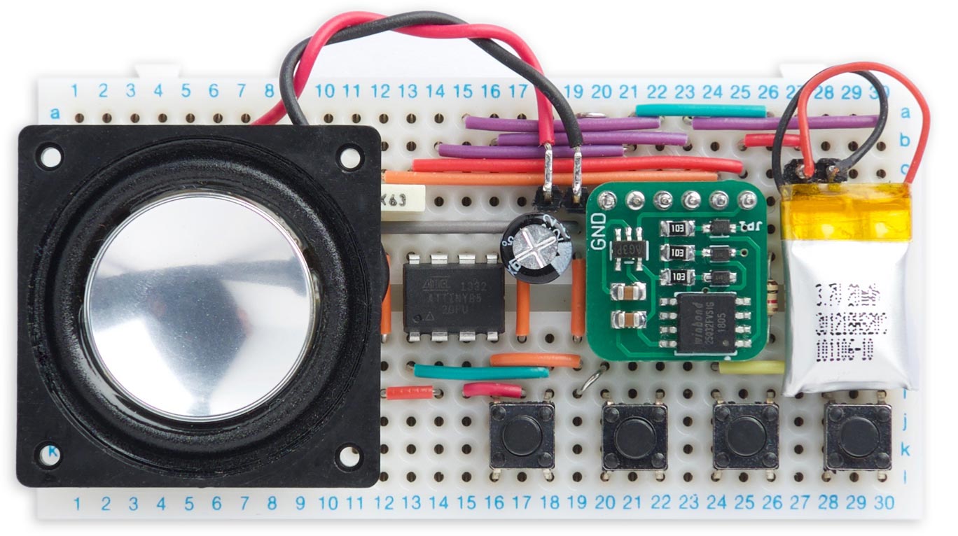
Four Sample Player plays one of four audio samples from a DataFlash chip at the press of a button.
For example, you could make it play one of four tunes, or one of four spoken phrases, at the press of a button. It avoids the need for an on/off switch by putting the ATtiny85 to sleep when the audio sample has finished playing.
Introduction
My earlier Audio Sample Player project played an audio sample from the ATtiny85's memory and output it to a loudspeaker. It played the audio from the 8kbytes of flash memory available on the ATtiny85, which limited the sample length to about one second.
This project uses a 4Mbyte DataFlash chip available for under 20 pence/cents each from AliExpress or eBay. The ATtiny85 reads the audio from the DataFlash chip and plays it through a loudspeaker, giving a maximum sample length of a total of 8 minutes and 44 seconds at a sample rate of 8kHz.
The circuit allows you to play one of four different samples by pressing the corresponding button. In theory you could provide a larger choice of samples, but I couldn't think of an easy way to connect more than four pushbuttons to the ATtiny85.
The circuit
Here's the circuit of the Four Sample Player:
Circuit of the Four Sample Player, incorporating the Simple DataFlash Board.
For convenience I based my prototype on my Simple DataFlash Board, and that section of the circuit is shown enclosed by a dashed line in the above diagram, but you could alternatively construct the whole circuit from scratch. The DataFlash board includes a regulator, to provide the 3.3V that the DataFlash chip needs, and logic level converters on the CS, MOSI, and SCK inputs. I powered the whole project from a 3.7V Lipo cell.
When a sample isn't playing the ATtiny85 goes to sleep, and the DataFlash chip is disabled and put in a power-down mode to save power. Three of the pushbuttons connect to I/O pins on the ATtiny85, and use pin-change interrupts to wake up the ATtiny85 and select the appropriate sample. These have no effect when a sample is playing. The fourth pushbutton connects to Reset, and is effective at any time.
There's no amplifier, so the volume depends on the supply voltage, VIN, and the sensitivity of the loudspeaker; generally, larger is better. Note that if you want to feed the output to an audio amplifier you should include a simple low-pass filter; otherwise the 250kHz carrier could damage the amplifier:
Connecting the output to an audio amplifier via a low-pass filter and volume control.
Setting up the audio samples
To play digitised audio from the DataFlash chip you first need to convert the audio files to an appropriate format, and then copy the audio data to the chip.
There are several ways you could do this. The procedure I used was to copy the audio files from my computer to an SD Card, and then use an Arduino Uno connected to an SD Card interface and the DataFlash card to copy the audio data across. This procedure is described in detail below.
Downsampling the audio samples
The first step is to downsample each of the four audio samples to 8-bit, mono, at an 8kHz sample rate, and save it as a WAV file. Many audio editors will do this; I used iTunes, as follows.
- Load the sample into your iTunes library.
- On the General tab in Preferences click the Import Settings... button.
- Select WAV Encoder, Custom....
- In the WAV Encoder dialog box select 8.000 kHz, 8-bit, Mono:
- Click OK to close each dialog box and the Preferences dialog box.
- Select the original track in iTunes.
- From the File menu choose Convert -> Create WAV Version.
The smaller version will be created as a separate track in iTunes, and you can drag it out onto the desktop to create a WAV file.
Copying the audio files to the DataFlash chip
Set up an Arduino Uno with a suitable SD Card interface. I used Adafruit's MicroSD card breakout board [1]. The board connects to GND and 5V, and the standard SPI pins: CLK (pin 13), DO (pin 12), DI (pin 11), and CS (pin 10). You also need to connect the DataFlash board to the Arduino Uno pins SCK (pin 3), MISO (pin 4), MOSI (pin 5), CS (pin 6), and VIN (pin 7, or +5V):
Connections for using an Arduino Uno to copy audio files from an SD card to a DataFlash board.
Here's the program I ran on the Arduino Uno to copy the files across: SD Card to DataFlash Program.
This simply copies the bytes from each WAV-format audio file, after skipping the first 44 bytes which are the file header. When the program runs it displays the end point for each file in the Serial Monitor, such as:
Start 0
Basso.wav 2486
Frog.wav 5380
Sosumi.wav 10291
Jasmine.wav 1415837
Finished
Make a note of these five numbers; you'll need to specify them in the Four Sample Player program.
The program
The audio player
The audio player takes advantage of the special 64MHz clock option in the ATtiny85 which you can use to drive Timer/Counter1 for fast digital-to-analogue conversion.
The program to interface to the DataFlash chip is essentially the same as the one in my article Simple DataFlash Program. However, that program used the standard Arduino ShiftIn() and ShiftOut() functions to read and write data. Those weren't fast enough to keep up with the 8kHz sample rate used for the audio output in this application, so I rewrote the Read() and Write() routines to access the ATtiny85 I/O pins more efficiently; the new routines can support a maximum sample rate of 10.75kHz.
I've left the routines for writing to the DataFlash chip, although they're not used in this application.
The audio player stores the start of each sample, and the end of the last sample, in the array Sizes[]. Set these to the values printed out by the SD Card to DataFlash Program; for example:
uint32_t Sizes[5] = { 0, 2486, 5380, 10291, 1415837 };
The setup routine
The two timer/counters are initialised in setup():
void setup() {
  // Enable 64 MHz PLL and use as source for Timer1
  PLLCSR = 1<<PCKE | 1<<PLLE;

  // Set up Timer/Counter1 for PWM output
  TIMSK = 0;                              // Timer interrupts OFF
  TCCR1 = 1<<CS10;                        // 1:1 prescale
  GTCCR = 1<<PWM1B | 2<<COM1B0;           // PWM B, clear on match
  OCR1B = 128;                            // 50% duty at start

  // Set up Timer/Counter0 for 8kHz interrupt to output samples.
  TCCR0A = 3<<WGM00;                      // Fast PWM
  TCCR0B = 1<<WGM02 | 2<<CS00;            // 1/8 prescale
  OCR0A = 124;                            // Divide by 1000

  set_sleep_mode(SLEEP_MODE_PWR_DOWN);
  ADCSRA = ADCSRA & ~(1<<ADEN);           // Disable ADC to save power
  PCMSK = 1<<mosi | 1<<miso | 1<<sck;     // Set up pin-change interrupts
}
The first section turns on the 64MHz Phase-Locked Loop (PLL), and specifies this as the clock source for Timer/Counter1. This is then set up in PWM mode, to make it act as a digital-to-analogue converter, using the value in OCR1B to vary the duty cycle. The frequency of the square wave is specified by OCR1C; we leave it at its default value, 255, which divides the clock by 256, giving a 250kHz square wave.
Timer/Counter0 is set up to generate an interrupt to output the audio data. The 8MHz clock is divided by 8 and 125, giving an 8kHz sample rate.
Finally, the setup() routine sets the sleep mode, and turns off the ADC to save power in sleep.
Playing a selected sample
The main loop plays the sample selected by the value of Play. After a reset this is 0, but Play is set to 1 to 3 by a pin-change interrupt from one of the three buttons B to D:
ISR (PCINT0_vect) {
  int Buttons = PINB;
  if ((Buttons & 1<<miso) == 0) Play = 1;
  else if ((Buttons & 1<<sck) == 0) Play = 2;
  else if ((Buttons & 1<<mosi) == 0) Play = 3;
  else Play = 0;
  GIMSK = 0;                              // Disable interrupts
}
The start address and size of the currently selected sample are read from the array Sizes[], and the Timer/Counter compare match interrupt is then enabled.
The interrupt service routine
The interrupt service routine outputs the audio data from the DataFlash, by calling DataFlash.ReadByte():
ISR (TIMER0_COMPA_vect) {
  char sample = DataFlash.ReadByte();
  OCR1B = sample;
  // End of data? Go to sleep
  Count--;
  if (Count == 0) {
    DataFlash.EndRead();
    TIMSK = 0;                            // Turn off interrupt
    StayAwake = false;
  }
}
The audio data bytes are counted by the global variable Count. When all the bytes have been output DataFlash.EndRead() is called, and StayAwake is set to false.
The main program in loop() then turns on the pin-change interrupt for the three buttons, and the processor is put to sleep. The current consumption in sleep measures 60µA on my prototype.
Compiling the program
I compiled the program using Spence Konde's ATTiny Core [2]. Choose the ATtiny25/45/85 option under the ATTinyCore heading on the Board menu. Then check that the subsequent options are set as follows (ignore any other options):
Chip: "ATtiny85"
Clock: "8 MHz (internal)"
B.O.D: "B.O.D. Disabled"
Choose Burn Bootloader to set the fuses appropriately. Then upload the program using ISP (in-system programming); I used Sparkfun's Tiny AVR Programmer Board; see ATtiny-Based Beginner's Kit.
Here's the whole Four Sample Player program: Four Sample Player Program.
- ^ MicroSD card breakout board on Adafruit.
- ^ ATTinyCore on GitHub.
blog comments powered by Disqus