Twelve PWM Outputs from an ATtiny85
19th February 2019
This project describes how to get 12 analogue PWM outputs from an ATtiny85, so you can drive 12 LEDs with individual control over each LED's brightness:
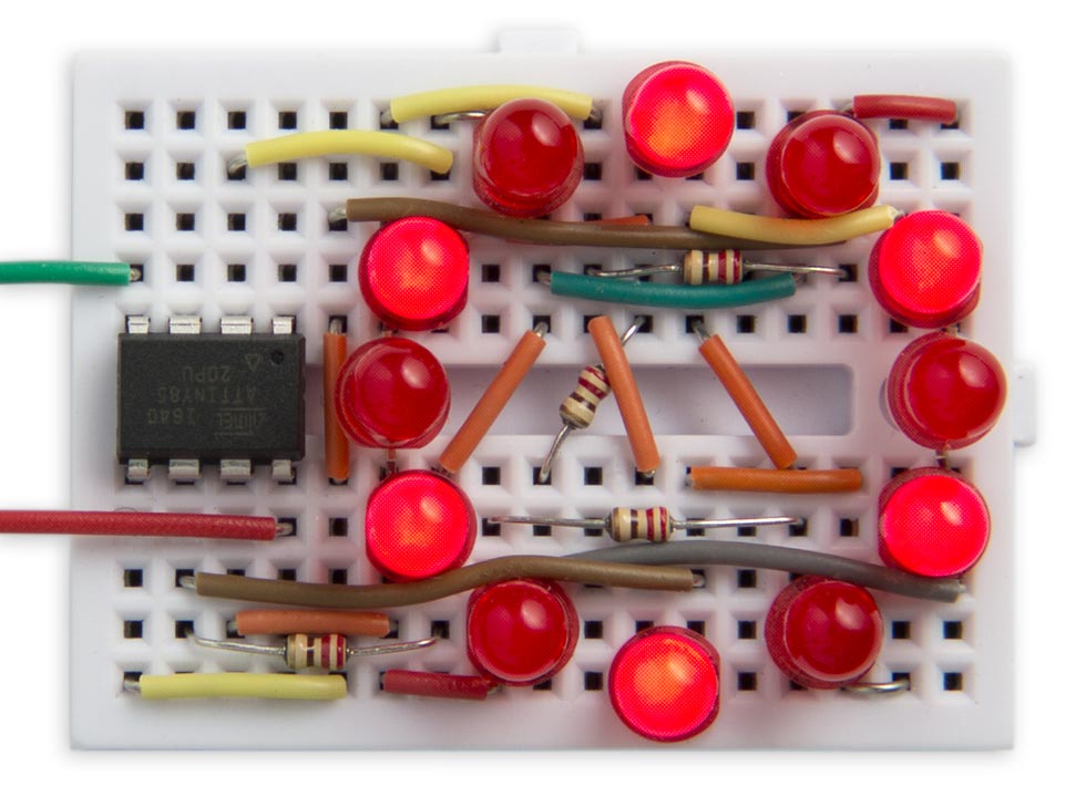
Twelve analogue PWM outputs controlling LEDs on an ATtiny85.
Each LED can be set to a brightness between 0 (off) and 63 (fully on). The demonstration program shows a rotating wave of light that moves around the circle.
The circuit could be used for a range of applications, from interactive LED displays, jewellery, or controlling the lights in a dolls house. It leaves one free I/O line on the ATtiny85, so you could control the light display from a sensor, or serial input.
Introduction
The usual way of getting PWM outputs on the ATtiny and ATmega chips is to use the built-in hardware timers to generate a waveform output with an appropriate mark-space ratio. This is how the Arduino analogWrite() command works. The ATtiny85 and ATtiny84 only have two timers, each of which has two outputs, so the maximum number of PWM outputs you can get this way from either of these chips is four.
An alternative way of getting PWM outputs is to use one of the timers to generate an interrupt; then, in the interrupt service routine you toggle each of the outputs as appropriate for the mark-space ratios you want to output. This requires a bit more programming, but lets you have PWM on every output. In the case of the ATtiny85 this could give you 5 PWM outputs, and on the ATtiny84 it could give you 11 PWM outputs.
This project goes one step further. It uses charlieplexing to allow you to connect an LED between each pair of I/O lines and then lets you control the brightness of each LED with PWM.
Charlieplexing
Charlieplexing takes advantage of the fact that each I/O line can have one of three states: low, high, or high-impedance when defined as an input. All the I/O lines are defined as inputs when no LEDs are illuminated, and to light one LED you take one I/O line low and another I/O line high. The LED at the intersection of those two lines will then light up.
The simplest way to visualise this is to draw a diagram, where each cell shows a combination of one I/O line low and another I/O line high. You can place an LED in each cell. The grey squares show positions where you can't connect an LED, because an I/O line can't be both high and low at the same time:
So the total number of LEDs you can control with four I/O lines is 12.
The circuit
Here's the circuit:
Circuit showing how to control 12 LEDs from an ATtiny85.
Each of the 12 LEDs connects to two of the ATtiny85 outputs, as shown above. I haven't drawn in the connections as it's clearer without. PB4 is unused, so it could be connected to a sensor or external circuit.
The whole circuit fits neatly on a mini breadboard from SparkFun [1] or HobbyTronics in the UK [2].
The program
The array Level[] is used to specify the level of each LED; each value can be between 0 and 63. Level[0] sets the brightness of LED 0 in the circuit diagram, and so on. For example, to give the display shown at the beginning of this article I used:
uint8_t Level[12] = {3, 63, 3, 63, 3, 63, 3, 63, 3, 63, 3, 63 };
The program uses an interrupt service routine to generate the PWM output on each LED. This is called by Timer/Counter1, which is set up in setup() to generate a compare match interrupt at 16kHz; each LED is therefore updated at 16000/64/4 or 62.5Hz, fast enough to avoid any visible flicker:
void setup() {
  // Set up Timer/Counter1 to multiplex the LEDs
  TCCR1 = 1<<CTC1 | 2<<CS10;          // Divide by 2
  GTCCR = 0;                          // No PWM
  OCR1A = 0;
  OCR1C = 250-1;                      // 16kHz
  TIMSK = TIMSK | 1<<OCIE1A;          // Compare Match A interrupt
}
This leaves Timer/Counter0 free for use by the Arduino functions delay() and millis().
The interrupt service routine then does all the work:
ISR(TIM1_COMPA_vect) {
  static uint8_t first, ramp, column, bits, colbit;
  ramp = (ramp+1) & 0x3F;             // Count from 0 to 63
  if (ramp == 0) {
    bits = 0x07;                      // All on
    column = (column + 1) & 0x03;
    first = column * 3;               // First LED in this column
    colbit = 1<<column;
  }
  if (Level[first] == ramp) bits = bits & 0x06;
  if (Level[first+1] == ramp) bits = bits & 0x05;
  if (Level[first+2] == ramp) bits = bits & 0x03;
  uint8_t mask = colbit - 1;
  uint8_t outputs = (bits & mask) | (bits & ~mask)<<1;
  DDRB = (DDRB & 0xF0) | outputs | colbit;
  PORTB = (PORTB & 0xF0) | outputs;
}
This divides the time into four slices, using the counter column, and during each slice the output corresponding to that column is taken low using colbit.
Each slice is divided into 64 subdivisions, using the counter ramp. When ramp is zero the three LEDs in the current column are turned on. As ramp counts up to 63 the level assigned to each LED then determines at what point it is turned off: a level of 0 turns it off immediately, whereas a level of 63 leaves it on for 63/64 of the time slice.
The variable bits specifies which of the three LEDs in the current column should be on in the current call of the interrupt routine. This is then split across the four I/O lines in the variable outputs, and written to the output port.
The interrupt service routine takes about 15ms to execute with an 8MHz clock, which limits the number of analogue levels we can support. I settled on 64 levels, which leaves adequate time for the processor to perform other functions between interrupts.
In the prototype due to the constraints of the breadboard I wasn't able to get the LEDs arranged in numerical order around the circle:
Order of the LEDs on the prototype breadboard.
This isn't a problem; I just used a second array, Order[], to redirect each element in the Level[] array. If you arrange the LEDs in sequential order you can omit the Order[] array.
Demo
To demonstrate the circuit the program sets the LEDs to a continuous range of brightnesses:
uint8_t Level[12] = {1, 1, 3, 7, 15, 31, 63, 31, 15, 7, 3, 1 };
The main program, in loop(), then shifts the levels along one position every tenth of a second, to give the appearance of a wave moving around the circle:
void loop () {
  // Wave demo
  uint8_t temp = Level[Order[11]];
  for (int i=11; i>0; i--) Level[Order[i]] = Level[Order[i-1]];
  Level[Order[0]] = temp;
  delay(100);
}
Current drive
The ATtiny85 datasheet recommends that the total drive current across all I/O ports should not exceed 60mA. An LED typically drops 1.8V, so with a 5V supply the current through each LED when fully on will be limited by the 220Ω resistor to (5 - 1.8)/220 or 14.5mA. However, each LED is only on for 1/4 of the time, because of the multiplexing, so the total current with all 12 LEDs at maximum brightness will be 43.5mA, safely within the maximum.
Compiling the program
I compiled the program using Spence Konde's ATTiny Core [3]. Choose the ATtiny25/45/85 option under the ATTinyCore heading on the Board menu. Then check that the subsequent options are as follows:
Chip: "ATtiny85"
Clock: "8 MHz (internal)"
B.O.D: "B.O.D. Disabled"
Timer 1 Clock: "CPU"
LTO (1.6.11+ only): "Disabled"
Choose Burn Bootloader to set the fuses appropriately. Then upload the program using ISP (in-system programming); I used Sparkfun's Tiny AVR Programmer Board; see ATtiny-Based Beginner's Kit.
Here's the whole ATtiny85 PWM program: ATtiny85 PWM Program.
Update
19th October 2021: I've updated a couple of lines in the interrupt service routine to prevent it from affecting the unused I/O line PB4, to allow you to use this for a separate function. Thanks to Frank Voogel for highlighting the problem.
- ^ Breadboard - Mini Modular on SparkFun.
- ^ Mini Breadboard from HobbyTronics.
- ^ ATTinyCore on GitHub.
blog comments powered by Disqus