Radio Time Code Clock
24th July 2014
I've always wanted to build a clock based on the radio time code signal. These are transmitted in several countries, giving a time code synchronised to an atomic clock, together with summer time adjustment, the date and day of week, and information about leap seconds. It seems such an elegant solution to providing accurate time, rather than having to maintain your own local time using a crystal or RTC module.
This post describes the simple radio clock I built, based on a low-cost 7-segment display and an ATtiny84:
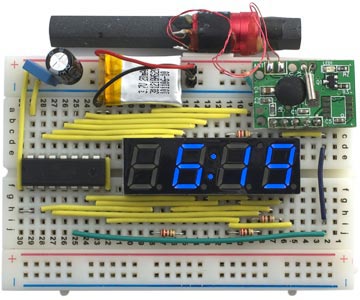
ATtiny84 Radio Time Code Clock.
Radio time module
The clock uses a radio time module available from PV Electronics [1] which takes a 3V to 5V supply and outputs the raw timecode on a single pin:
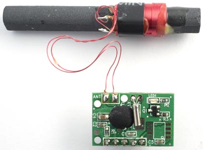
The module I used receives UK time from the MSF 60kHz transmitter at Anthorn, Cumbria [2], and is suitable for use throughout the UK and in parts of Europe. Modules are also available for the DCF 77.5kHz transmitter in Frankfurt, which covers large parts of Europe [3], and the WWVB 60kHz transmitter near Fort Collins, Colorado, USA [4].
Driving the display
The clock uses a low-cost four-character 7-segment LED display module available from SparkFun, or Hobbytronics [5] and Proto-PIC [6] in the UK. I wanted to make the clock as simple as possible, so I decided against using the ATmega328 used in the Arduino, but the ATtiny85 was unsuitable because it doesn't have enough pins without additional components. The ideal choice seemed the ATtiny84, which is available in a compact 14-pin DIL package, and has 11 I/O pins (not using Reset).
A quick calculation shows that we need 4 pins for the four digit lines, and 7 pins for the 7 segments, which uses up all 11 pins and doesn't leave a pin for the clock input. Also, it would be nice to be able to display the colon, decimal points, and degree symbol. At this point I nearly gave up, but reading an excellent article about Charlieplexing gave me hope [7].
I thought about whether Charlieplexing could be used in this application. Charlieplexing makes use of the fact that each I/O pin can have three states; high, low, or open (defined as an input). This allows you to connect two LEDs to each distinct pair of I/O lines, so you can control n x (n-1) LEDs with n I/O lines. For example, you can potentially control 20 LEDs with the five I/O lines on an ATtiny85.
However, the four-digit 7-segment display module arranges the individual LEDs in a 4 x 8 matrix, with the 4 digit anodes and 8 segment cathodes commoned. At first sight this prevents us from using Charlieplexing to reduce the number of pins you need below the 12 you'd expect. The trick was to find combinations that we don't need to use:
- For a clock, we only need to display the digits 1 or 2 in the leftmost display position, digit 0, neither of which use segment f. We can therefore use the same pin low to drive the f segments, or high to drive digit 0.
- We don't need to display the rightmost decimal point, so we can use the same pin low to drive the dp segments, or high to drive digit 4.
- The colon and degree dot provide independent access to their anode and cathode, so we can access them by connecting them between two of the digit-drive lines.
These three tricks enabled me to drive all four 7-segment displays, plus the colon, degree dot, and two decimal points, using just 10 I/O pins, leaving one free for the clock input. Note that this technique could be used for any other application that doesn't need to display more than 3999, like a digital voltmeter.
Circuit
Here's the full circuit, which shows this in more detail. For consistency with the program I've labelled the digits 0 to 3:
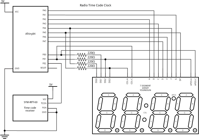
ATtiny84 Radio Time Code Clock circuit.
The Port A pins are used to drive the segments, so the definition for a complete digit can use a single write to the PORTA register. For convenience I wired up the segments to the Port A pins in whatever order fitted most easily on the breadboard, and used a routine ReorderBits(), called once during setup(), to reorder the bits in the character definitions to correspond to the way I'd wired them.
Display update
The 7-segment display is updated in the background, from the four values in Buffer[], using interrupts generated by Timer/Counter0. For example:
Buffer[0] = 1;
Buffer[1] = 2;
Buffer[2] = 3;
Buffer[3] = 4;
will display "1234". We set up the timer for fast PWM mode, counting up to OCR0A, and with a second interrupt generated by a compare match with OCR0B. Here's the code to set up the timer/counter:
TCCR0A = 3<<WGM00; // Fast PWM, 0 to OCRA
TCCR0B = 1<<WGM02 | 2<<CS10; // clock/8
OCR0A = 249; // CTC mode at 500Hz
TIMSK0 = 1<<OCIE0A | 1<<OCIE0B; // Compare match interrupt enable
Timer/Counter0 interrupt A turns on the display, by taking the appropriate digit anode high:
// Timer 0 interrupt A - turns on display
ISR(TIM0_COMPA_vect) {
  pinMode(Digits[digit], OUTPUT);
  digitalWrite(Digits[digit], HIGH);
}
Timer/Counter0 interrupt B calls DisplayNextDigit() which turns off the display, and sets up the segment data for the next digit:
// Timer 0 interrupt B - turns off and sets up display
ISR(TIM0_COMPB_vect) {
  DisplayNextDigit();
  milliseconds += 2;
  Average();
}
The value in compare register OCR0B determines how long the digit is on for, and is used to adjust the brightness of the display; see below.
This interrupt service routine also increments the millisecond counter, and calls Average() to read the radio data input.
Finally, here's the DisplayNextDigit() routine:
// Gets called every 2 msec
void DisplayNextDigit() {
  int Segs, Char;
  // Turn display off
  pinMode(Digits[digit], INPUT);
  digit = (digit+1) % ndigits;
  Char = min(Buffer[digit],charArrayLen-1);
  Segs = charArray[Char & 0x7F];
  // Display colon?
  if ((Char & 0x80) && (digit==3)) {
    pinMode(Digits[2], OUTPUT);
    digitalWrite(Digits[2], LOW);
  }
  // Equalise brightness
  OCR0B = (pop(Segs) + 4) * 16  ; // Max 198
  DDRA = 0;     // All inputs
  PORTA = Segs ^ 0xFF; // 1 = high
  DDRA = Segs;  // 1 = output
}
It turns the display off, reads the segment definitions for the next character, writes them to PORTA, and then configures the lit segments as outputs.
If we're displaying digit 3, and the top bit of the character in the buffer is set, we also display the colon, which has its cathode connected to the digit 2 pin.
Equalising the display brightness
For simplicity the clock circuit uses a single current-limiting resistor per digit. This has the effect that digits with few segments, like "1", would be brighter than ones with more segments, like "8". However, using PWM mode allows us to compensate for this as follows.
The number written to the Timer/Counter0 compare register B determines the brightness of the next character to be displayed. It can have values between 0, minimum brightness, and about 198, maximum brightness. To equalise the display brightness I set the digit brightness using pop(), which counts the number of "1" digits in the segment data, and hence the number of lit segments in the digit:
OCR0B = (pop(Segs) + 4) * 16; // Max 198
Here's the definition of pop() [8]:
// Count the population or number of '1's in x as binary
int pop(unsigned char x) {
  x = (x & 0x55) + ((x>>1) & 0x55);
  x = (x & 0x33) + ((x>>2) & 0x33);
  return (x & 0x0f) + (x>>4);
}
You could also use the OCR0B value to dim the whole display at night.
Decoding the radio time code
Before designing the routines to decode the time code signal I looked at several radio clock programs that have already been published, but they seemed a bit complicated for what I wanted. Although the MSF time code includes the date and day of week, I was only interested in decoding the time. Also, most other approaches I've seen use the signal from the clock module to generate an interrupt, but this makes the decoding complicated because you have to calculate pulse widths, and seems the wrong approach if you have a potentially noisy signal, because you'll have to deal with spurious interrupts.
My approach was to read the input every 2 msec, and store the last 8 values. This was handled by the Average() routine which was called from the display refresh interrupt:
// Buffers last 8 states of radio output (16msec)
void Average () {
  boolean Bit = digitalRead(RadioPin);
  BitCount = BitCount - ((BitBuffer & 0x80) >> 7) + Bit;
  BitBuffer = (BitBuffer<<1) | Bit;
}
The global variable BitCount gives the number of high bits in the last 8 samples; values over 4 indicate a high level, and below 4 a low level.
The main loop of the program waits for the pulse that marks the start of a minute, and then reads the appropriate time codes that occur once per second during the minute.
In practice I found that a significant proportion of the time codes were corrupted, probably due to radio interference, and although the signal includes a parity bit, some corrupted time codes have correct parity, so that's not a reliable guide. The clock therefore maintains its own time, and only updates the time from the radio signal when it receives two successive time codes with correct parity that differ by one minute.
After first switching on the clock counts from 12:00 until it receives its first radio time code. Whenever it successfully receives a time code it indicates this by displaying the colon on the display.
Development
The radio clock was built on a small prototyping board, and programmed using the SparkFun Tiny AVR Programmer, which I've talked about in an earlier article: ATtiny-Based Beginner's Kit. To use the ATtiny84 with the Arduino IDE you need to install a core giving the pin definitions for the ATtiny chips; the one I used for this project was the Arduino-Tiny core [9]. I used the ATtiny84 with its default 1MHz internal clock.
The program is just over 2Kbytes, so would fit on an ATtiny44, and possibly an ATtiny24 with a bit of optimising.
You can get the full listing here: Radio Time Code Clock Program.
Addendum
25th July 2014: I've corrected a couple of mistakes in the wiring on the circuit diagram above.
- ^ MSF 60 KHz Time Receiver Module With Antenna on PV Electronics.
- ^ Time from NPL on Wikipedia.
- ^ DCF77 on Wikipedia.
- ^ WWVB on Wikipedia.
- ^ 4-Digit 7-Segment Display - Blue on Hobbytronics.
- ^ 4-Digit 7-Segment Display - Blue on Proto-PIC.
- ^ Charlieplexing with LED dot matrix modules on 110111100001.
- ^ Hamming weight on Wikipedia.
- ^ Arduino-Tiny core on Google Code.
blog comments powered by Disqus