Silver Dollar Game
8th December 2023
At about this time of year I like to design a game or puzzle project, for a bit of fun in the festive season. This one is a logic game called Silver Dollar Game in which the aim is move five silver dollars, represented by LEDs, along a strip of 12 positions:
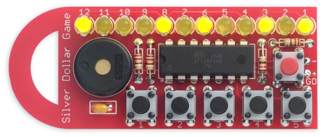
The Silver Dollar Game, in which you move five silver dollars represented by LEDs
along a row of 12 positions.
Initially five random LEDs light up representing the silver dollars. You take turns with the device to move one silver dollar to any blank position to its right. The last player able to move wins the game.
The circuit is based on an ATtiny84A processor, and it goes into a low-power sleep mode after a delay to avoid the need for an on/off switch.
Introduction
The Silver Dollar Game is related to the game Nim [1], often played with heaps of matchsticks, and it was first described in mathematician John Horton Conway's book "On Numbers and Games" [2].
The original game is played with silver dollars on a strip of squares, and the players take turns in moving one silver dollar to any blank position to its right. In their turn a player must make a move. When one player can't move, because the silver dollars are in a traffic jam at the right hand end of the strip, the other player wins.
In this version the silver dollars are represented by lit LEDs, and you play first. To move a silver dollar you press the button corresponding to its position, once for each step you want to move it. For example, to move the second silver dollar three steps press button 2 three times. If you try to make an invalid move the speaker beeps. Once you've made your move press the GO button, and the device will then make its move, according to the same rules. If you win the speaker plays a tune to congratulate you.
The game starts with a different arrangement of the five silver dollars each time, and the device will always try to beat you, but the starting positions are chosen so that it's always possible for you to win if you make the right moves.
Example game
Here's an example game, starting with the LEDs 11, 5, 4, 2, and 1 lit:
After five moves the player wins by moving LED 6 to 5. The device now has no legal move because the LEDs are all as far right as they can go.
The circuit
Here's the circuit, which is close to the layout on the PCB:
Circuit of the Silver Dollar Game, based on an ATtiny84A.
I chose to base the game on an ATtiny84A which provides exactly the right number of I/O pins, and it's available in a through-hole DIP package making it easy to solder. The program is also small enough to fit on an ATtiny24A or ATtiny44A, although I haven't actually tested those.
The LEDs are 3mm size, and I chose yellow LEDs to represent the silver dollars. Any colour LED should be fine, but they should all be the same colour. A suitable supplier is Bright Components in the UK [3].
The LEDs are driven from the four I/O pins PA0 to PA3 using charlieplexing. I arranged the LEDs to simplify the PCB layout which explains the rather haphazard order, but this is easily accommodated by an array in the software. The following table shows which LED lights up when you take one I/O line high and the other I/O line low:
The push buttons are 6mm square through-hole types [4]. I chose a red button for the GO button, to distinguish it.
The circuit can be run from any suitable 3V to 5V supply, such as a 3.7V Lipo cell; I used a pair of AAA batteries in series.
► Parts list
Construction
You could build the circuit on a breadboard, but I decided to go straight to designing a PCB for it, and based it on the format of my earlier Five LEDs Puzzle PCB project. As with that circuit I designed it to use through-hole components, so it would be suitable as a soldering project for a beginner.
The PCB will accommodate either of two widely available piezo speakers: the TDK PS1240P02CT3 [5], or the ABT-402-RC [6].
I've brought the programming connections to a standard 2x3 pin pad so you can connect to it with a set of six pogo pins. I give details of how to make a suitable Pogo probe below. Alternatively you could temporarily solder six wires to the ISP pad, and remove them when you've uploaded the program.
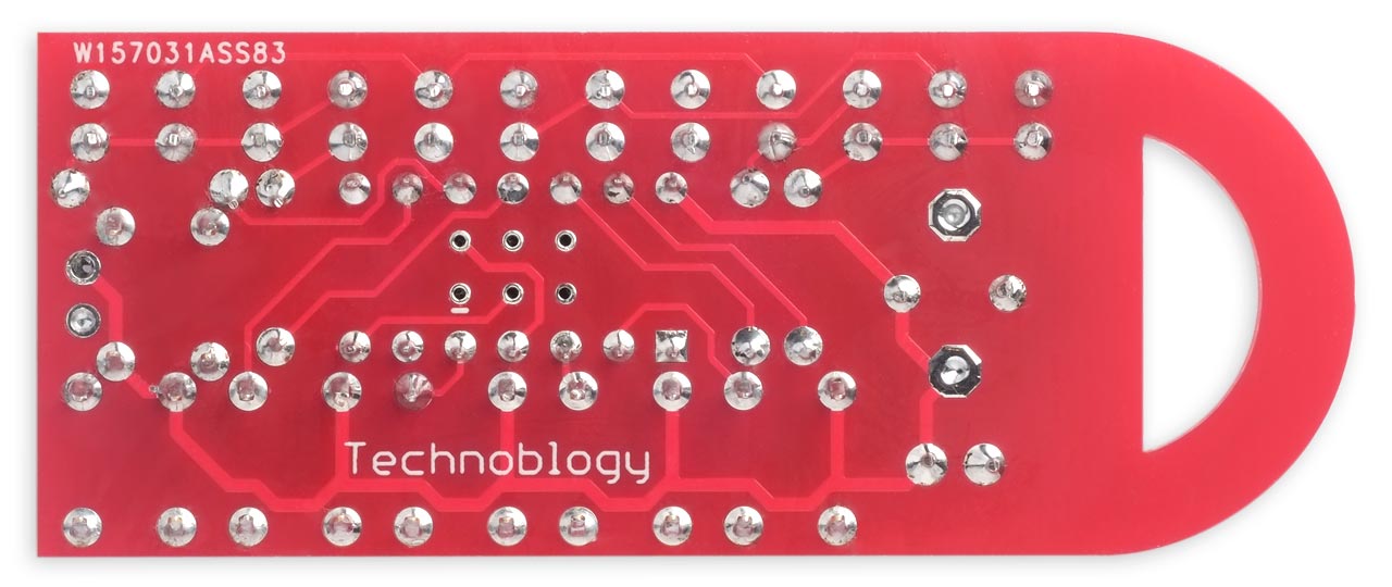
The back of the Silver Dollar Game PCB showing the ISP programming pad.
The PCB is designed to fit on top of a battery pack containing two AAA batteries; I fitted it in place with two double-sided self-adhesive foam pads:
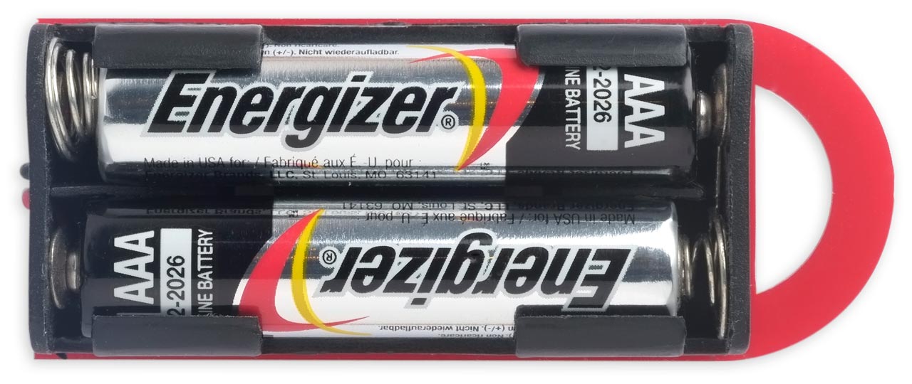
A battery holder for two AAA cells fits to the back of the Silver Dollar Game.
The program
The Silver Dollar Game takes advantage of the ATtiny84A's two Timer/Counters to multiplex the LEDs, and generate tones in the speaker.
Multiplexing the display
The display consists of a row of 12 LEDs, controlled by the four I/O lines PA0 to PA3 using charlieplexing. Timer/Counter0 is used to generate a 1000Hz interrupt which is used to multiplex the display. The display is set up using the routine SetupDisplay():
void SetupDisplay () {
  TCCR0A = 2<<WGM00;                            // CTC mode; count up to OCR0A
  TCCR0B = 0<<WGM02 | 3<<CS00;                  // Divide by 64
  OCR0A = 124;                                  // Divide by 125 -> 1000Hz
}
This generates an interrupt that calls DisplayNextRow() to display the next row of three LEDs:
ISR(TIM0_COMPA_vect) {
  DisplayNextRow();
  Timer--;
  Timeout--;
}
The Timer/Counter0 interrupt service routine also decrements the global variables Timeout and Timer which are used to provide a sleep timeout and a millisecond delay respectively:
void Delay (int count) {
  cli(); Timer = count; sei();
  int now;
  do {
    cli(); now = Timer; sei();
  } while (now > 0);
}
The cli() and sei() calls are needed to avoid the possibility of Timer being decremented by the interrupt service routine while you're updating it or reading it.
The 12-bit global variable LEDs specifies which LEDs should be lit up. The routine DisplayNextRow() reads the bit numbers for the current row from the array LED[row][col] and sets the appropriate port bits:
void DisplayNextRow() {
  static uint8_t Cycle;
  uint8_t row = Cycle++ & 0x03;
  uint8_t bits = 0;
  for (int col=0; col<4; col++) {
    int led = LED[row][col];
    if ((Flash == led) && ((Cycle & 0x80) == 0)) led = 0;
    if (led != 0) {
      uint8_t bit = LEDs>>(led-1) & 1;
      bits = bits | bit<<col;
    }
  }
  DDRA = (DDRA & 0xF0) | 1<<row | bits;         // Make row and active cols outputs
  PORTA = (PORTA & 0xF0) | bits;                // Make cols high - leave pullups on
}
Sound effects
Timer/Counter1 is used to play tones through the piezo speaker to provide feedback about correct and invalid moves, and to play a tune when the player or game has won.
The routine SetupSpeaker() sets up Timer/Counter1 in CTC mode to generate an output on OC1B (PA5), which is connected to the piezo speaker. Its frequency is controlled by register OCR1A:
void SetupSpeaker () {
  DDRA = 1<<Speaker;                            // Make output
  TCCR1A = 0;
  TCCR1B = 1<<WGM12 | 3<<CS10;                  // 8MHz/64/142 = 880Hz = A5
}
The well-tempered scale of notes C5 to B5 are defined by the divisors in the array Scale[]:
//                  C   C#  D   D#  E   F   F#  G   G#  A   A#  B
uint8_t Scale[] = {239,226,213,201,190,179,169,160,151,142,134,127};
The routine PlayNote() plays a note and duration specified by the parameters:
void PlayNote (int note, int millis) {
  TCCR1A = 1<<COM1B0 | 0<<WGM10;
  OCR1A = Scale[note] - 1;
  Delay(millis);
  TCCR1A = 0;
}
For example, the note A5 uses the divisor in Scale[9] which is 142. With the 8MHz clock this gives a frequency 80000000/64/142 = 880Hz.
I've only catered for one octave, but you could extend this to cover multiple octaves by choosing a lower prescaler, and then shifting the divisors up to generate the lower octaves.
The routines Beep(), Click(), Celebrate(), and Comiserate() call PlayNote() to generate the various sound effects.
Utility routines
The Silver Dollar Game uses two utiities; PseudoRandom() generates a random 12-bit number:
uint16_t PseudoRandom () {
  static uint16_t RandomSeed = 1;
  uint16_t temp = RandomSeed & 1;
  RandomSeed = RandomSeed >> 1;
  if (temp == 1) RandomSeed = RandomSeed ^ 0xD34;
  return RandomSeed;
}
PopCount() returns the number of '1' bits in a 16-bit binary number:
int PopCount(uint16_t x) {
  x = (x & 0x5555) + ((x>>1) & 0x5555);
  x = (x & 0x3333) + ((x>>2) & 0x3333);
  x = (x & 0x0f0f) + ((x>>4) & 0x0f0f);
  return (x & 0x00ff) + (x>>8);
}
You could implement this using a for loop, but the above routine is more efficient.
How the Silver Dollar Game position is represented
The positions of the five Silver Dollars are represented by the array Dollar[]. This makes it easy to check for valid moves, and move the dollars on the track.
The routine UpdatePosition() converts these positions to the appropriate '1' bits in the 12-bit global variable LEDs:
void UpdatePosition () {
  LEDs = 0;
  for (int i=0; i<Dollars; i++) {
    LEDs = LEDs | 1<<(Dollar[i]-1);
  }
}
This is used by the display routine to generate the LED display.
Choosing the starting position
The Silver Dollar Game chooses a random starting position, with two constraints:
- To avoid trivial games, the leftmost counter must start on cell 12 or 11.
- It should be possible for the player to win from this position.
There are actually 444 possible starting positions that fulfill these requirements.
The routine RandomPosition() chooses a random 12-bit number with five '1' bits, and with a '1' in at least one of top two bits:
void RandomPosition () {
  int pos;
  do {
    pos = PseudoRandom();
  } while (pos >> 10 == 0 || PopCount(pos) != Dollars);
  // Convert to dollar positions
  int dol = 0;
  for (int i=12; i>0; i--) {
    if (pos>>(i-1) & 1 == 1) Dollar[dol++] = i;
  }
}
The routine RandomPossiblePosition() then ensures that the position is one that the player could win from, given a series of correct plays:
void RandomPossiblePosition () {
  do {
    RandomPosition();
  } while (NimSum() == 0);
  UpdatePosition();
}
To avoid spoiling the challenge I've explained how the program chooses the best move, and how you can always beat it, in a separate article: Silver Dollar Game: How to Win.
Making the device's move
The device's move is calculated by the routine FindBestMove():
int FindBestMove () {
  int allmoves = 0, wins = 0, windollar = 0, winmove = 0, anydollar = 0, anymove = 0;
  for (int i=1; i<=Dollars; i++) {              // For each dollar
    int moves = Dollar[i-1] - Dollar[i] - 1;
    int start = Dollar[i-1];
    for (int m=1; m<=moves; m++) {
      Dollar[i-1] = start - m;
      allmoves++;
      if ((PseudoRandom() % allmoves) == 0) { anydollar = i; anymove = m; }
      if (NimSum() == 0) {
        wins++;
        if ((PseudoRandom() % wins) == 0) { windollar = i; winmove = m; }
      }
    }
    Dollar[i-1] = start;
  }
  if (wins > 0) return windollar<<8 | winmove;
  else return anydollar<<8 | anymove;
}
If there is a winning move it chooses it; otherwise it chooses any valid move.
The number of winning moves is counted in wins, and the number of valid moves in allmoves. We store the dollar that needs to be moved in windollar or anydollar, and the number of moves it needs to make in winmove or anymove.
We could just choose the first such move in each case, but this would give rather predictable play. Instead, when we encounter another move of either type, we discard the previous choice and choose it in preference with a probability of 1/n. By trying some examples you should be able to reassure yourself this really does do what we want, namely to choose randomly between any of the wins moves, or allmoves moves, with equal probability.
Going to sleep
To avoid the need for an on/off switch the device goes to sleep if you don't press a key for 30 seconds. The current consumption in sleep is about 0.05µA, which is negligible. To wake the game from sleep press the GO button.
The routine Sleep() puts the processor to sleep:
void Sleep () {
  DisplayOff();                                 // Display off
  PCMSK0 = 1<<PCINT6;                           // Enable Go (PA6) interrupt
  sleep_enable();
  sleep_cpu();                                  // Go to sleep until button press
  // Continue here after interrupt
  PCMSK0 = 0;                                   // Disable Go (PA6) interrupt
  DisplayOn();
  while ((PINA>>Go & 1) == 0);                  // Wait for Go to be released
  Delay(100);
}
The routine ResetTimeout() resets the Timeout counter, protected from interrupts:
void ResetTimeout () { cli(); Timeout = SleepTimeout; sei(); }
The routine MaybeSleep() checks the global variable Timeout, decremented by the display multiplexer, and when it reaches zero calls Sleep():
void MaybeSleep () {
  cli(); int now = Timeout; sei();
  if (now > 0) return;
  Sleep();
  // Come here when wake up
  ResetTimeout();
}
Playing the game
The main flow of control for playing the game is in loop():
void loop () {
  bool playerwon = false, computerwon = false;
  // Wait for Go
  Cylon();
  // Choose position
  RandomPossiblePosition();
  // Next round
  do {
    int last = 0; bool moved = false, pressedgo = false;
    // Player move
    ResetTimeout();
    do {
      bool go = GoPressed();
      int button = CheckButton();
      if (go) {
        ResetTimeout();
        if (moved) {
          Flash = 0;
          pressedgo = true;
        } else Beep();                          // Haven't moved yet
      } else if (button != 0) {
        ResetTimeout();
        if ((last == 0 || last == button) && CanMove(button)) {
          MoveButton(button);
          moved = true;
          last = button;
        } else Beep();                          // Illegal button or can't move
      }
      MaybeSleep();
    } while (!pressedgo);                       // Drop through after wake
    // Has player won?
    if (WinPosition()) {
      playerwon = true;
      Celebrate();
    } else {
      ComputerMove();
      if (WinPosition()) {
        computerwon = true;
        Comiserate();
      }
    }
  } while (!(playerwon || computerwon));
}
Uploading the program
You'll need an ISP programmer to upload the program to the Silver Dollar Game PCB. To make it easier to upload the program I've brought the programming connections to a standard 2x3 pin pad so you can connect to it with a set of six pogo pins. You can convert a USBasp programmer to a pogo-pin programmer as described below (repeated from Twinkling Pendant).
Making a pogo-pin programmer
If you get a USBasp programmer with a 10-pin to 6-pin adapter for ISP programming you can replace the 6-pin socket with a set of six pogo pins [7] as follows:
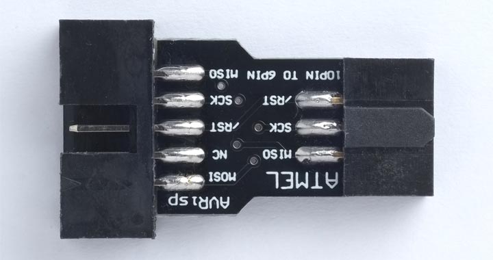
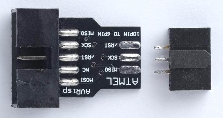
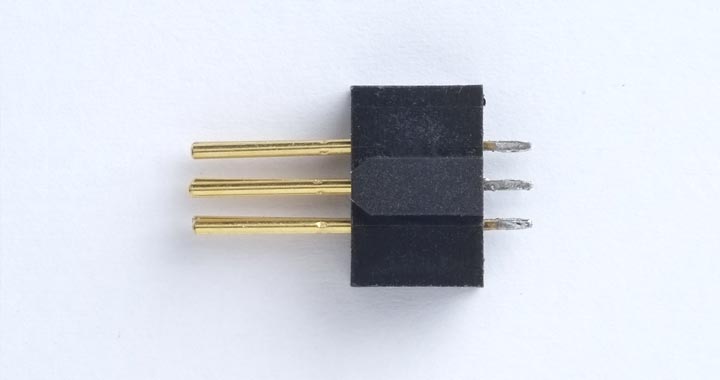
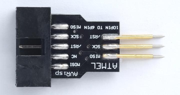
- Unplug the 10-pin to 6-pin adapter from the USBasp ribbon cable.
- Unsolder the 6-pin header socket from the adapter.
- Push the pogo pins into the header socket, point side first, to use the socket to hold the pins in the correct alignment.
- Solder the six pogo pins to the 10-pin to 6-pin adapter board, three on each side, and then remove the header socket.
You can then plug the ribbon cable back into the adapter board, and use the pogo pins to connect to the six pads on the PCB.
Compiling and uploading
As with the earlier version, compile the program using Spence Konde's ATTiny Core [8]. Choose the ATtiny24/44/84(a) (No bootloader) option under the ATTinyCore heading on the Board menu. Then check that the subsequent options are set as follows (ignore any other options):
Chip: "ATtiny84(a)"
Clock: "8 MHz (internal)"
Connect to the board using an ISP programmer; as described above I used a USBasp programmer; another option is Sparkfun's Tiny AVR Programmer Board.
Choose Burn Bootloader on the Tools menu to set the fuses appropriately. Then choose Upload on the Sketch menu to upload the program
Because the piezo speaker is connected to the MISO pin, it buzzes when you upload a program. This doesn't do any harm, and in fact provides useful feedback that the upload is happening.
Resources
Here's the Silver Dollar Game program: Silver Dollar Game Program.
Get the Eagle files from GitHub so you can make yourself a board: https://github.com/technoblogy/silver-dollar-game.
Or order a board from OSH Park here: Silver Dollar Game.
Or order a board from PCBWay here: Silver Dollar Game.
- ^ Nim on Pencil and Paper Games.
- ^ Conway, John Horton. On Numbers and Games. New York: Academic Press, 1976.
- ^ 20x 3mm Yellow Diffused LED on Bright Components.
- ^ Alcoswitch FSM4JH Tactile Switch on Farnell.
- ^ TDK PS1240P02CT3 on Farnell.com.
- ^ Multicomp Pro ABT-402-RC on Farnell.com.
- ^ Pogo pins "Needle Head" (10 pack) on Adafruit.
- ^ ATTinyCore on GitHub.
blog comments powered by Disqus