Mega Tiny Time Watch [Updated]
7th January 2020
This is the latest in my series of minimalist watches using 12 LEDs, arranged like a clock face, to show the time analogue-style. This one takes advantage of the fact that Microchip's new 1-series ATtiny microcontrollers incorporate a real-time clock, which can be run from an external crystal to keep accurate time while the main processor is put to sleep:
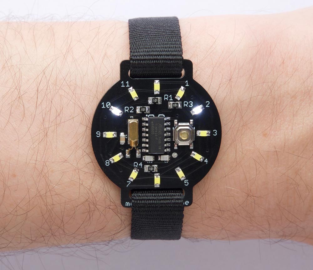
The Mega Tiny Time watch based on an ATtiny414; it's ten to two.
To show the time you press the button on the watch face, and it lights up LEDs to show the time like the hour and minute hands on a clock. The LEDs flash to distinguish the hours and minutes, and show intermediate times. The watch keeps time to within a few seconds a month, while giving a battery life of several years.
Introduction
My earlier Tiny Time 2 Watch used Maxim Integrated's DS2417 RTC chip to keep time while the processor was put to sleep, to save power. Since I designed that, Microchip have released their 1-series ATtiny chips that incorporate a crystal-controlled real-time clock; this can keep time while the processor is asleep, avoiding the need for a separate RTC chip. Spence Konde calls these the "Mega Tiny" range; hence the name of this watch.
I based this watch on the 14-pin ATtiny414, which has 4K bytes of flash memory, and has an RTC peripheral that supports an external crystal. In this design there are a few I/O pins spare, so you could extend the watch with other features; see Further suggestions below.
As with my earlier watch, to show the time you press the button on the watch face, and the time is then displayed for five seconds. It lights one LED to show the hour, and flashes one or two other LEDs to show the minutes to the nearest minute by altering the rate at which each of the LEDs flash. Here are some examples:
Examples of how the Mega Tiny Time watch displays the time.
For consistency with analogue watches, the Tiny Time Watch displays times later than half past the hour by lighting the next hour number. If only one LED lights up you know that both hands are pointing to the same hour mark.
The total power consumption with no display is just 1µA, giving an estimated battery life of over 10 years from a single CR2016 battery! Obviously this is reduced if you check the time frequently.
The circuit
Here's the circuit of the Tiny Time 2 watch, laid out like the circuit board:
Circuit of the ATtiny414-based Mega Tiny Time watch.
The crystal is a standard 32.768 kHz quartz watch crystal; I chose a MS1V-T1K micro crystal [1], but I expect any 32.768 kHz crystal would be suitable. A 3.2 X 1.5 mm SMD crystal would also fit across the pads on the PCB.
To calculate the capacitor values I used the formula C = 2(CL - CS), where CL is the load capacitance 6pF, and CS is the stray capacitance which is usually estimated to be 2.5pF on a PCB. This gives C=7pF. I used the closest available value, 6pF.
The LEDs are 0805 size, and for this version of the watch I chose white LEDs to contrast with the black circuit board. I got mine from Bright Components in the UK, who sell them for under £1 for ten [2]. Any colour LED should be fine, but they should all be the same colour.
I arranged the LEDs to simplify the PCB layout which explains the rather haphazard order, but this is easily accommodated by an array in the software. The following table shows which LED lights up when you take one I/O line high and the other I/O line low:
The button is a miniature SMD push button available from Sparkfun [3], available from Proto-PIC in the UK [4].
The battery is a 20mm coin cell. Given the low current consumption I decided to use the slimmer CR2016 cell, and found a suitable SMD battery holder on Mouser [5]. Alternatively you could use a CR2032 battery, with an SMD 20mm coin cell holder available from Sparkfun [6], or from Proto-PIC in the UK [7].
NOTE: If a child could play with this watch please bend the tabs on the coin cell holder, or glue in the coin cell, so the cell can't be removed and swallowed.
► Parts list
Construction
I designed the board in Eagle and sent it to PCBWay for fabrication. Here's the layout (from the OSH Park preview):
See the end of the article for links to download the board files or order a board.
I built the watch using SMD components, with all the components apart from the battery holder soldered to the front of the board. The ATtiny414 was SOIC, and I used 0805 resistors and LEDs, so they should be relatively easy to solder by hand:
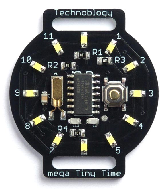
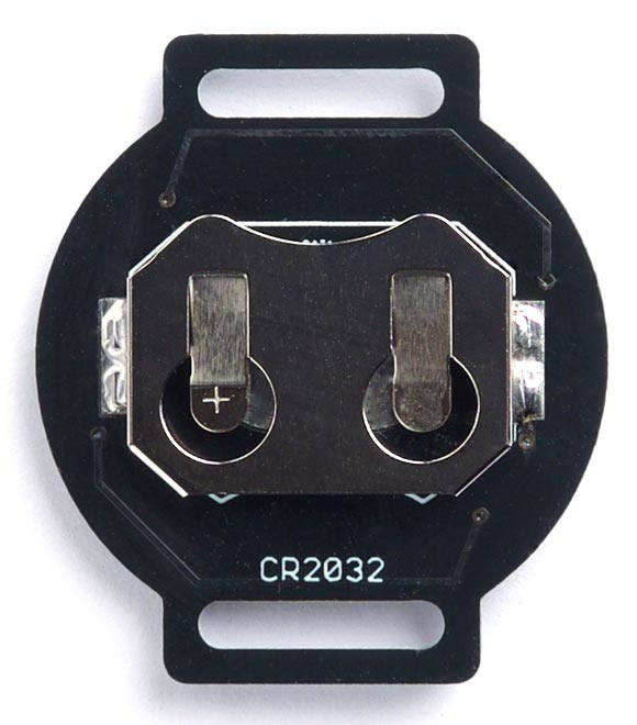
The front and back of the completed Mega Tiny Time watch circuit board.
The LEDs should all be soldered with the same orientation, with the negative sides facing the centre of the board.
I used a Youyue 858D+ hot air gun at 250°C to solder the SMD components onto the front of the board, and then finally soldered the battery holder onto the back of the board using a conventional soldering iron. If you don't have a hot air gun you should be able to solder the SMD components with a bit of care using a fine-tipped soldering iron.
I found a suitable 12mm wide thread-through watch strap from a German supplier [8].
The program
This section explains the various sections of the Tiny Time Watch program.
Real-Time Clock
As in my earlier project New ATtiny Low Power, the aim is to keep the processor asleep most of the time to minimise the watch's power consumption.
From the ATtiny414 datasheet I realised that there were two possible ways to use the 1-series ATtiny Real-Time Clock peripheral in this application. It could run as a Real-Time Counter, keeping a 16-bit count of the number of elapsed seconds in the RTC CNT Count register while the processor stays asleep. Alternatively it could run as a Periodic Interrupt Timer (PIT), generating an interrupt to wake up the processor briefly every second and increment a variable to count the number of seconds.
In theory the CNT approach should give slightly lower power consumption, because the processor only needs to be woken up when you're displaying the time, but I couldn't get it to work; the CNT register didn't seem to get incremented when the processor was asleep. However, the PIT approach worked perfectly, and the difference in power consumption is probably minimal. If I get the CNT method working I'll post it as an update.
Setting up the RTC to use an external crystal is more complicated than you might expect, because the Clock Controller is protected from accidental change by Configuration Change Protection (CCP), so before each change you have to enable the action first. Fortunately there's an application note that explains how to do this, and my code is based on one of the examples in that note [9].
The display
The 12 LEDs are driven by the four I/O lines PA1, PA4, PPA5, and PA6. The array Pin[6][6] specifies how the LEDs are connected to the five I/O lines:
int Pins[6][6] = {{ -1, -1, -1,  8,  6,  4 },
                  { -1, -1, -1, -1, -1, -1 },
                  { -1, -1, -1, -1, -1, -1 },
                  {  7, -1, -1, -1, 11,  9 },
                  {  0, -1, -1, 10, -1,  2 },
                  {  5, -1, -1,  3,  1, -1 }};
The first row of the array specifies which LEDs have their cathodes connected to PA1: the LED at 8 o'clock has its anode connected to PA4, the LED at 6 o'clock has its anode connected to PA5, and the LED at 4 o'clock has its anode connected to PA6. The values in the array corresponding to PA2 and PA3 are set to -1, as these aren't connected to any LEDs; it was simpler to use a larger array than write code to compensate for this.
I used Timer/Counter TCB running at 250 Hz to multiplex the display. This is set up by the routine DisplaySetup() as follows:
void DisplaySetup () {
  // Set up Timer/Counter TCB to multiplex the display
  TCB0.CCMP = 19999;                                  // Divide 5MHz by 20000 = 250Hz
  TCB0.CTRLA = TCB_CLKSEL_CLKDIV1_gc | TCB_ENABLE_bm; // Enable timer, divide by 1
  TCB0.CTRLB = 0;                                     // Periodic Interrupt Mode
  TCB0.INTCTRL = TCB_CAPT_bm;                         // Enable interrupt
}
The interrupt service routine simply calls DisplayNextRow(), decrements the global variable Timeout, and increments the global variable Offset used when initially setting the time:
ISR(TCB0_INT_vect) {
  TCB0.INTFLAGS = TCB_CAPT_bm;                        // Clear the interrupt flag
  DisplayNextRow();
  Timeout--;
  Offset++;
}
Two additional routines are used to turn the display on and off:
void DisplayOn () {
  // Turn off all the pullups
  PORTA.PIN0CTRL = 0;
  PORTA.PIN1CTRL = 0;
  PORTA.PIN4CTRL = 0;
  PORTA.PIN5CTRL = 0;
  PORTA.PIN6CTRL = 0;
  TCB0.INTCTRL = TCB_CAPT_bm;                         // Enable interrupt
}

void DisplayOff () {
  TCB0.INTCTRL = 0;                                   // Disable interrupt
  PORTA.DIR = 0;                                      // All PORTA pins inputs
  // Turn on all the pullups for minimal power in sleep
  PORTA.PIN0CTRL = PORT_PULLUPEN_bm;                  // UPDI
  PORTA.PIN1CTRL = PORT_PULLUPEN_bm;
  PORTA.PIN4CTRL = PORT_PULLUPEN_bm;
  PORTA.PIN5CTRL = PORT_PULLUPEN_bm;
  PORTA.PIN6CTRL = PORT_PULLUPEN_bm;
}
Display multiplexing
The routine DisplayNextRow() works as follows:
void DisplayNextRow() {
  Cycle++;
  uint8_t row = Cycle & 0x03;
  if (row > 0) row = row + 2;                         // Skip PA2 and PA3
  uint8_t bits = 0;
  for (int i=0; i<6; i++) {
    if (Hours == Pins[row][i]) bits = bits | 1<<(i+1);
    if (Fivemins == Pins[row][i]) bits = bits | 1<<(i+1);
  }
  PORTA.DIR = 1<<(row+1) | bits;                      // Make outputs for lit LED
  PORTA.OUT = bits;                                   // Set outputs high
}
Up to two LEDs can be lit at once. The LED specified by the variable Hours is used to show the hours, and is displayed continuously. The LED specified by the variable Fivemins is used for the minutes.
The bottom two bits of the variable Cycle determine which row is being displayed. For a given row the array Pins[row][i] is checked to see if any of the LEDs in that row need to be displayed. If so, the appropriate bits are set in the variable bits. This is then written to the port.
To test the the LEDs you can run the following loop() function instead of the one in the listing:
void loop () {
  Fivemins = 12;
  Hours = (Hours + 1) % 12;
  delay(1000);
}
This will light each of the 12 LEDs in turn, one per second.
Setting the time
When you first apply power to the watch (ie insert the battery) it runs SetTime() to allow you to set the time to the nearest second. It works as follows: wait until the current time is an exact multiple of five minutes, and insert the battery. The watch will then start from 12:00, stepping through the display five minutes at a time. When the watch shows the time you inserted the battery, press the Show Time button. The watch will account for the additional time it took you to set the time, and then display the current time. It's now ready for use.
The SetTime() routine keeps incrementing the variable secs by 300, equivalent to five minutes, displaying the time for a second between steps. At each step it writes the value of secs to the global variable Secs, with an offset added to account for the elapsed time since starting the procedure.
void SetTime () {
  unsigned int secs = 0, offset = 0;
  ButtonEnable();
  while (!ShowTime) {
    Fivemins = (secs/300)%12;
    Hours = ((secs+1800)/3600)%12;
    // Write time to global Secs
    Secs = secs + offset;
    DisplayOn();
    MyDelay(Tickspersec);
    DisplayOff();
    offset++;
    secs = secs + 300;
  }
}
Show Time button
The ATtiny414 is normally in sleep mode, which draws negligible current. The Show Time button is connected to PA2 which is defined with a pullup and pin-sense interrupt by ButtonEnable():
void ButtonEnable () {
  PORTA.PIN2CTRL = PORT_PULLUPEN_bm;                   // Pullup
  PORTA.PIN2CTRL = PORTA.PIN2CTRL | PORT_ISC_LEVEL_gc; // Trigger low level
}
This is done in two separate instructions to ensure that the pullup is active before the interrupt is enabled.
Pressing the button generates a pin-sense interrupt handled by this interrupt service routine:
ISR(PORTA_PORT_vect) {
  PORTA.PIN2CTRL = PORT_PULLUPEN_bm;                  // Disable button
  PORTA.INTFLAGS = PORT_INT2_bm;                      // Clear PA2 interrupt flag
  ShowTime = true;
}
This disables the pin-sense interrupt, to avoid contact bounce, and sets the global variable ShowTime to true.
Displaying the time
The time is actually displayed by the main routine loop():
void loop () {
  unsigned int secs;
  if (ShowTime) {
    cli(); secs = Secs; sei();
    Hours = ((secs+1800)/3600)%12;
    Fivemins = 12;
    int Mins = (secs/60)%60;
    int From = Mins/5;
    int Count = Mins%5;
    DisplayOn();
    for (int i=0; i<5-Count; i++) {
      Fivemins = From; MyDelay(Tickspersec/5);
      Fivemins = 12; MyDelay(Tickspersec/5);
    }
    for (int i=0; i<Count; i++) {
      Fivemins = (1+From)%12; MyDelay(Tickspersec/5);
      Fivemins = 12; MyDelay(Tickspersec/5);
    }
    DisplayOff();
    ShowTime = false;
    ButtonEnable();
  }
  sleep_cpu();
}
This first copies the global variable Secs into a local variable secs with interrupts disabled, to ensure that Secs isn't updated by the RTC interrupt while this is happening. It then calculates the values of the variables Hours and Mins.
The first for loop flashes the previous five-minute mark and the second for loop flashes the next five-minute mark, according to where the time is between the two marks, for a total of five flashes.
As explained above, the Mega Tiny Time Watch displays times later than half past the hour by lighting the next hour number; this is implemented with the correction +1800 in the calculation of Hours. If you don't like this behaviour omit the +1800 in that line.
Compiling the program
Compile the program using Spence Konde's megaTiny Core on GitHub. Choose the ATtiny1614/1604/814/804/441/404/241/204 option under the megaTinyCore heading on the Board menu. Check that the subsequent options are set as follows (ignore any other options):
Chip: "ATtiny414"
Clock Speed: "5MHz"
Programmer: "jtag2updi (megaTinyCore)"
Then upload the program to the watch circuit using a UPDI programmer. I used my UPDI Programmer Stick; alternatively you can make a UPDI programmer from an Arduino Uno, or other ATmega328P-based board, as described in Make UPDI Programmer. The UPDI pin is brought to a small pad on the front of the PCB, and I held the UPDI cable in contact with this while programming the board, to avoid needing to solder a wire permanently.
You can ignore the error "Cannot locate flash and boot memories in description".
Here's the whole Mega Tiny Time Watch program: Mega Tiny Time Watch Program.
Making a PCB
Get the Eagle files for the PCB from GitHub so you can make yourself a board, at: https://github.com/technoblogy/mega-tiny-time-watch.
Or order a board from PCBWay here: Mega Tiny Time Watch.
Or order a board from OSH Park here: Mega Tiny Time Watch.
Further suggestions
There are four unused I/O pins in this design, so you could extend the watch to add other features. For example, you could add an AM/PM LED, or further buttons to choose other modes such as a stopwatch, date display, or an alarm using a piezo beeper.
Updates
8th November 2020: I've updated the code to fix two bugs that affected setting the time:
Occasionally on inserting the battery to set the time the 12 o'clock LED would just turn on for a second and then turn off. This was solved by enabling the pullup on the PA2 button input before enabling the interrupt on that input.
Also, setting the watch to a time of between 11:00 and 12:00 would result in a time five minutes too early. This was due to overflow in the variable Offset, and is solved by counting the offset in seconds rather than ticks.
Thanks to user reh4c1 for reporting these problems.
16th March 2021: Added a note about calculating the crystal capacitors.
- ^ MS1V-T1K 32.768kHz Micro Crystal on RS-Online.
- ^ 10x White 0805 Surface Mount (SMD/SMT) LED on Bright Components.
- ^ Mini Push Button Switch - SMD on SparkFun.
- ^ Mini Push Button Switch (SMD) on Proto-PIC.
- ^ BAT-HLD-002-SMT Linx Technologies Battery Holder on Mouser.
- ^ Coin Cell Battery Holder - 20mm (SMD) on SparkFun.
- ^ Coin Cell Battery Holder - 20mm (SMD) on Proto-PIC.
- ^ Watch strap 12mm black nylon/textile one-piece strap on Watchbandcenter.com.
- ^ TB3213 Getting Started with RTC on Microchip.
blog comments powered by Disqus