Sound Lab - a Simple Analogue Synthesiser
30th May 2024
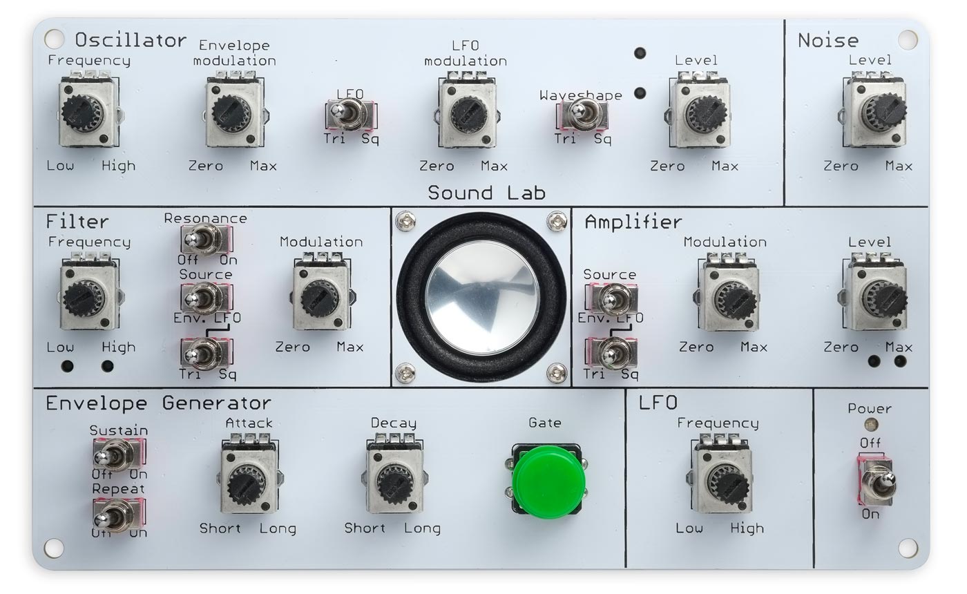
Sound Lab is an analogue synthesiser, consisting of six modules that can be combined in a variety of ways. It uses a single printed circuit board that doubles as the front panel and wiring, with surface-mount components and PCB-mounted controls to make the construction as easy as possible:
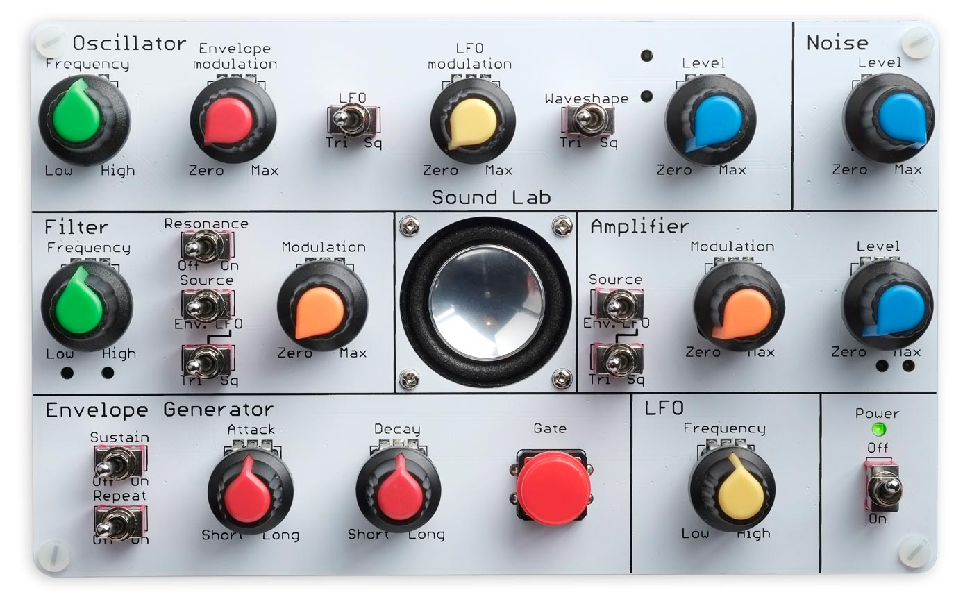
Sound Lab: a single-board analogue synthesiser using
surface-mount components and board-mounted controls.
It's capable of making a wide range of sounds, including natural sounds such as weather sounds, animal noises, speech-like sounds, and mechanical sounds such as alarms, sirens, engines, and machinery. For examples with audio samples see Sound Lab - Example Sounds.
The Sound Lab measures 158 x 96 x 27mm, small enough to be comfortably held in one hand while you're using it.
Introduction
Sound Lab is inspired by a classic analogue synthesiser, the WP-20, which was designed in around 1980 by Ray Wilson and Ron Romeo, and marketed by their company Waveform Processing [1].
To make this synthesiser easy to construct we've based it on a single PCB, with the potentiometers and switches mounted to the top of the board, and all the other components mounted on the reverse. This virtually eliminates the need for any manual wiring.
Unlike most of my previous projects Sound Lab is entirely analogue, and it doesn't include any microcontrollers or digital logic. It uses surface-mount resistors, capacitors, diodes, and integrated circuits, and it should be possible to solder them with a small-tipped soldering iron. However it will definitely be easier to use a hot air gun and solder paste.
With careful sourcing of components it should be possible to build a Sound Lab for about £60/$60 including the PCB.
The design
Sound Lab consists of six interconnected modules, as shown in the following diagram:
A block diagram of the Sound Lab modules.
The modules are explained in the following sections:
Oscillator
The main signal source is the Oscillator. This is a voltage-controlled oscillator that generates a square wave or triangle wave whose frequency can be controlled by a voltage input. One possible input is a static voltage, to give a fixed frequency output. Alternatively, feeding a varying voltage into the Oscillator modulates it to produce a sound that varies in frequency. Tones produces by the Oscillator can be modulated by the LFO and/or Envelope Generator.
Modulating a tone's frequency with the LFO can produce a vibrato effect. Modulating a tone with the Envelope Generator can give a rising and falling tone, like a siren.
Range: 6Hz to 4kHz.
Noise
A second signal source is the white-noise generator. When filtered by the Filter and gated by the Amplifier this can produce a variety of natural and mechanical sounds, such as wind, cymbals, and gunshots.
LFO (Low-Frequency Oscillator)
The LFO generates a low-frequency waveform. The LFO can be used to modulate the Oscillator, Filter, and/or the Amplifier.
Range: 2.4Hz to 1280Hz.
Envelope Generator
The Envelope Generator can create a changing voltage with an envelope that includes a rising part, called the Attack, and a falling part, called the Decay, each of which can be adjusted independently. Like the LFO, the Envelope Generator can be used to modulate the Oscillator, Filter, and/or the Amplifier.
Filter
The outputs from the Oscillator and Noise modules passes through the Filter. This filters the waveform with a low-pass filter whose cutoff frequency depends on the voltage input. It can also be made to resonate, like striking a bell.
Amplifier
Finally, the output from the Filter passes to the Amplifier. This can be used to modulate the amplitude of the sound. Using the Amplifier to modulate a sound with the LFO can produce a tremolo effect. Modulating a sound with the Envelope Generator can produce a sound that rises and falls in amplitude.
Loudspeaker
The output from the voltage-controlled Amplifier is fed to a loudspeaker, or the audio output.
Guided tour
Once you've built Sound Lab, take this guided tour to get familiar with some of its features.
Start with all the potentiometers turned fully ante-clockwise, and all the switches in their left position:
A pure tone
- Turn the Oscillator Frequency to its mid position.
- Turn the Oscillator Level to its mid position.
- Turn the Amplifier Level to its mid position.
You should now hear a high-pitched tone.
Modulate the tone with the LFO
- Turn the Oscillator LFO modulation to its mid position.
- Turn the LFO Frequency to its mid position.
This uses the LFO (Low Frequency Oscillator) to modulate the frequency of the tone.
Modulate the tone with the Envelope Generator
- Turn the Oscillator LFO modulation to zero.
- Turn the Envelope modulation to its mid position.
- Turn the Envelope Generator Attack to its mid position.
- Turn the Envelope Generator Decay to its mid position.

When you press the Gate button the frequency of the tone will be modulated by an envelope, and you can adjust the Attack and Decay of the envelope by adjusting the corresponding controls.
- Turn the Repeat switch on to repeat the envelope without needing to press the Gate button.
Further examples
For some more complex examples, with audio samples, see Sound Lab - Example Sounds.
The circuit
The following sections give the full circuit of each of the modules in Sound Lab.
Oscillator
Circuit of the Oscillator module.
The Oscillator circuit generates a triangle or square wave whose frequency is determined by the voltage at the input. The main part of the circuit is a Voltage-Controlled Oscillator using the two op amps IC3C and IC3D from a quad LM3900 op-amp package, and is based on a circuit from the Texas Instruments LM3900 Application Note [2]. The LM3900 is a Norton op amp, which differs from standard op amps in that the voltage on the output is proportional to the current difference between the inputs rather than the voltage difference between the inputs.
The op amp IC3C charges the timing capacitor C6 at a constant current, which depends on the voltage at the junction of R11 and R15. IC3D acts as a Schmitt trigger; when it reaches threshold the output goes low, turning on Q4 and reversing the direction of the current into C6. The output of IC3C provides a triangle wave, and the output of IC3D a square wave.
The Oscillator has a linear response of approximately 550Hz per volt at the input, giving a range from 6Hz to about 4kHz for inputs from 0 to 9V.
A further gate, IC3A, acts as a mixer to allow you to combine three signals at the input of the Oscillator. One input can be a static voltage, which will give a steady tone; this can then be modulated by signals from the LFO and the Envelope Generator.
The Waveform switch, S9, chooses between a triangle waveform and a square waveform:
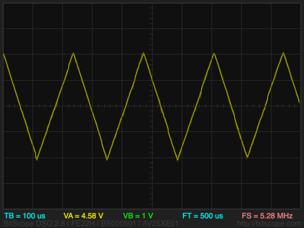
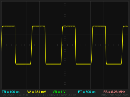
The output of the Oscillator is fed to the Filter via a level control.
Noise
Here's the circuit of the noise module:

Circuit of the voltage doubler and Noise module.
The noise is generated by a reverse-biased transistor emitter junction, biased to 18V. The collector is intentionally left unconnected.
The noise is amplified by an LM3900 op amp, and then fed to the VCF.
To avoid the need for an additional battery or power supply, the 18V bias voltage is generated by a voltage doubler created from a CMOS 555 oscillator.
The output of the Noise module is fed to the Filter via a level control.
LFO (Low-Frequency Oscillator)
Circuit of the Low-Frequency Oscillator (LFO) module.
The LFO in the original WP-20 used an oscillator based on three CD4001 gates, but we've chosen a design that gives better triangle waveforms using two conventional LM324 op amps, the quad version of the LM358, using a circuit from the Onsemi LM358 Datasheet [3].
A third op amp is used to amplify the triangle wave to the same amplitude as the square wave.
Envelope Generator
Circuit of the Envelope Generator module.
The Envelope Generator is based on a CMOS LM555D Timer in monostable mode. When the Gate button S3 is pressed the Trigger input of the 555 timer is brought low, which takes the output Q high, and allows C2 to charge. Current flows through D1 through the Attack control, RV36, and charges C16. This voltage is fed through the op-amp buffer, and then through R2 to the 555 timer Threshold input. When this reaches 2/3 of Vcc the output goes low, and C16 is discharged through D2 and the Decay control, RV37.
When the Sustain switch S2 is closed, the 555 timer output will remain high as long as the Gate button S3 remains closed. When the Repeat switch S5 is closed the Envelope Generator will retrigger itself through R32 at the end of each Attack/Decay cycle. If both switches are closed the Sustain switch takes priority. Note that because the Repeat function is level sensitive it will stop working if the battery voltage is low.
Filter
Circuit of the Filter module.
The outputs from the Oscillator module and Noise module are fed to a voltage-controlled low-pass filter created by C13, C14, R25, and Q3 in the feedback loop of the op-amp IC2A. As the current into the base of Q3 increases, the emitter to collector resistance decreases, causing the cutoff frequency of the filter to increase.
Damped oscillation in the filter circuit adds color to the sound of the waveform. Closing S4 adds C15 into the feedback loop of the op amp, adding more damping to the circuit and reducing its resonance.
Amplifier
Circuit of the Amplifier module.
The output from the Filter module is fed to a voltage-controlled amplifier consisting of Q2 and the op amp IC2C. When P8 is fully ante-clockwise, at +9V, Q2 is turned fully on. Turning P8 clockwise modulates the amplitude by either the LFO or the Envelope Generator, depending on the position of S8.
The output is fed via the main level control, P9 to the audio output, or via an LM386 power amplifier to the loudspeaker. R36 gives the level control an approximately logarithmic characteristic.
Components
The most significant components that affect the price of the final unit are the potentiometers, switches, and PCB. The following sections provide some suggestions for sourcing these and the other components.
Potentiometers
The circuit uses 12 potentiometers with the same specification, as follows:
- Size: 9mm series. This is available from several manufacturers, including Bourns.
- Mounting: rear mount.
- Resistance: 200kΩ linear, sometimes marked B204 (A is logarithmic).
- Bushing: This is the threaded section to allow the potentiometer to be mounted in a panel. Since these are mounted directly on the PCB the ideal is bushingless, to allow the knob to sit as close to the PCB as possible.
- Detent: No detent.
- Shaft length: The ideal is 20mm if you are planning to fit knobs, or 15mm (the shortest available) if you are going to use them without knobs. You could use ones with 25mm or 30mm shafts if you are prepared to cut them down. Note that the shaft length is measured from the base of the potentiometer, where it sits on the PCB.
- Shaft type: How the shaft is terminated. The options are: flatted or D (only suitable for matching knob), or knurled 18/40 teeth (suitable for use with fingers, or with a suitable knob).
The following list gives some suitable potentiometers that are available at the time of writing, with comments on the suitability of each:
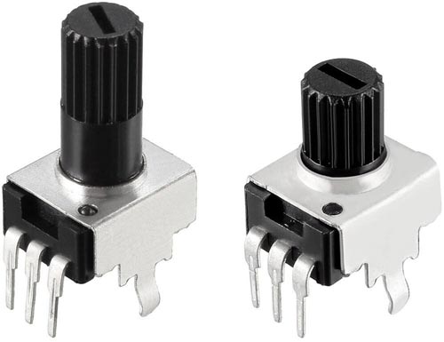
- Uxcell 784958561850 [4]: Ideal low-cost potentiometers with 20mm shaft and knurled 18 teeth (above left).
- Uxcell 784958562048 [5]: As above but with shorter 15mm shaft (above right).
- Bourns PTV09A-4030U-B204 [6] or CUI devices PT01-D130K2-B204 [7]: The shaft is 30mm so it will extend well above the panel, unless you cut it down. The shaft style is knurled, 40 teeth, which means it's usable without a knob.
Switches
The circuit uses 10 SPDT toggle switches. They should be miniature PCB mount types, with a terminal spacing of 0.1" (2.5mm) to fit the PCB. Bushingless is ideal. Note that standard toggle switches with 4.7mm terminal spacing are not suitable.
Here are some suitable alternatives:
Printed Circuit Board
The cheapest source I could find for a PCB of this size was Elecrow in Shenzhen, China [11], and they also conveniently offer an acrylic laser cutting service, which I used for the back panel. The PCB becomes a substantially smaller part of the parts cost if you are making several units.
Resistors and capacitors
The resistors are all 0805 size, 5%. Apart from the electrolytic, C23, all the capacitors are 0805 size MLCC (Multilayer Ceramic Capacitors). It's generally recommended that capacitors are rated about 25% above the voltage across them, so they should all have a rating of at least 16V, apart from C35 and C36 in the voltage doubler circuit which should be at least 25V. I got most of the resistors and capacitors from a book of 0805 components that I already had [12], but I've given suggested part numbers in the table below if you need to buy them.
LED
The power indicator LED is a reverse-mount 1206 LED, but a standard 1206 LED mounted upside-down works equally well.
Loudspeaker
I've chosen a 32mm square loudspeaker, type [13]. or Visaton BF 32 [14].
Knobs
For the prototype shown in the above photos I used 12 knobs sourced from AliExpress [15], using five different colours to identify the different signal paths. An alternative colourful option is multi-colour knobs from Adafruit [16] or their suppliers.
Power supply
Sound Lab is designed to work from a single 9V power supply, and it draws on average 100mA, depending on what sounds you make. The simplest solution is to power it from a 9V PP3 battery. A non-rechargeable PP3 battery can provide 1200mAh [17], but it's probably more economical to use rechargeable NiMH PP3 batteries. The best I've found is the Ansmann 300mAh battery [18], and they also make a PP3 charger [19].
Sound Lab also provides a power jack to allow you to power it from an external 9V power supply; this disconnects the internal battery. The power supply should have a 5.5mm diameter cylindrical plug with a 2.1mm hole, centre positive. You can also use a USB-C power supply that supports Power Delivery at 9V with a suitable cable, such as Adafruit's one [20]. There's no regulator on the Sound Lab board, so it shouldn't be powered with more than 9V.
Here's the full parts list (click to expand):
► Parts list
Construction
I created a PCB in Eagle, and ordered a set of boards from Elecrow. I recommend adding a note to your order to draw attention to the 30mm cutout for the loudspeaker. I built and tested three prototypes; in the process found a few minor mistakes on the PCB, but I've corrected these on the board provided below in Resources.
All the resistors, capacitors, and the LED are 0805 size, and the other components are in SOIC packages, so it should be possible to assemble the board with a fine-tipped soldering iron, but I used a Youyue 858D+ hot air gun at 325°C with Chip Quik SMD291AX10T3 solder paste. I recommend soldering the SOIC packages first, followed by the passive components, and finally mount the potentiometers, switches, and connectors using a conventional soldering iron.
The front of the assembled board, before fitting the knobs.
I fitted the loudspeaker on the back of the PCB with four M2 x 8mm self-tapping screws, and fastened the 9V battery holder just to the right of the loudspeaker with double-sided foam self-adhesive pads:
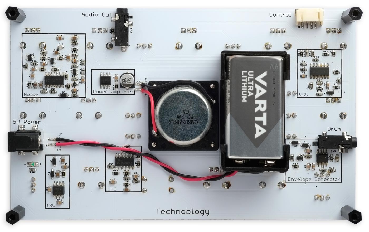
Back view of Sound Lab showing the loudspeaker and battery holder wiring.
I fitted the acrylic back panel to the board with four M3 x 22.5mm threaded pillars and eight nylon M3 screws.
Testing
I recommend the following procedure for initially testing the board:
- Apply +9V between Vcc and GND while monitoring the current consumption. Anything above about 30mA indicates a possible short, so disconnect quickly and check for shorts between tracks on the board.
- Check for about 16.5V across C29.
- The noise output, across P5, should be about 140mV RMS.
- Check the Guided tour above, to ensure that each of the modules is working as expected.
Frequently asked questions
I've made an amazing sound. Can I save it?
The simplest solution is to take a photo of the synth with your mobile phone, showing the pot and switch positions. Another option is to make a drawing of the pot and switch positions.
Can I play it like a musical instrument?
Yes, you can give a live performance by adjusting the controls to alter the sound. You can also trigger sounds with a contact on the Drum input, or you can control the frequency by connecting a voltage to the Control input.
Are there any practical applications for Sound Lab?
Here are a few:
- Learning about how sounds are constructed.
- Creating interesting sounds for incorporating into musical compositions.
- Creating sound effects for school drama and amateur dramatics.
- Play Sound Lab Simon; one player creates an interesting sound, then shuffles the controls and the other player has to try and reproduce it.
Can I interface to it via Midi?
No, it's not that sort of synthesiser.
Resources
Get the Eagle files for the PCB here: https://github.com/technoblogy/sound-lab
Here's the whole circuit diagram in a single image: Sound Lab Circuit Diagram.
Acknowledgements
I am very grateful to Chris Jordan, who collaborated with me on the development of this project, and without whose help it would not have been possible.
Update
3rd June 2024: I've added details of the Control connector to the parts list, and given more details about the 3.5mm jack sockets.
- ^ Waveform Processing WP-20 on Music from Outer Space.
- ^ The LM3900: A New Current-Differencing Quad of Plus or Minus Input Amplifiers on ti.com.
- ^ Single Supply Dual Operational Amplifiers Datasheet on onsemi.com.
- ^ Potentiometer 200K Ohm Variable Resistors from gadgetskingdom on eBay.
- ^ Potentiometer 200K Ohm Variable Resistors from gadgetskingdom on eBay.
- ^ Bourns PTV09A-4030U-B204 on Mouser.
- ^ CUI Devices PT01-D130K2-B204 on Digikey.
- ^ Switch, PCB SPDT Vertical - MC2MS1T2B2M2RE on CPC Farnell.
- ^ MULTICOMP PRO 2MS1T2B2M2RE on Farnell.
- ^ Dailywell 2MS1T2B2M2RES on Mouser.
- ^ Elecrow.
- ^ SMT/SMD 0805 Resistor and Capacitor Book on Adafruit.
- ^ CUI devices MS0321KLX on Mouser.
- ^ Visaton BF 32 on Mouser.
- ^ 17x14mm Bicolor Knob on AliExpress.
- ^ Multi-Color Micro Potentiometer Knob on Adafruit.
- ^ VARTA Lithium 9V Block 6LR61 on Amazon.
- ^ Ansmann 9V Block Battery 300mAh NiMH on Amazon.
- ^ Ansmann Powerline 9V Charger on Amazon.
- ^ USB Type C 3.1 PD to 5.5mm Barrel Jack Cable - 9V 5A Output on Adafruit.
blog comments powered by Disqus