Big Time
28th January 2020
This is a giant digital clock, featuring four large LED displays that provide the time in a format you can read from the other side of the room:
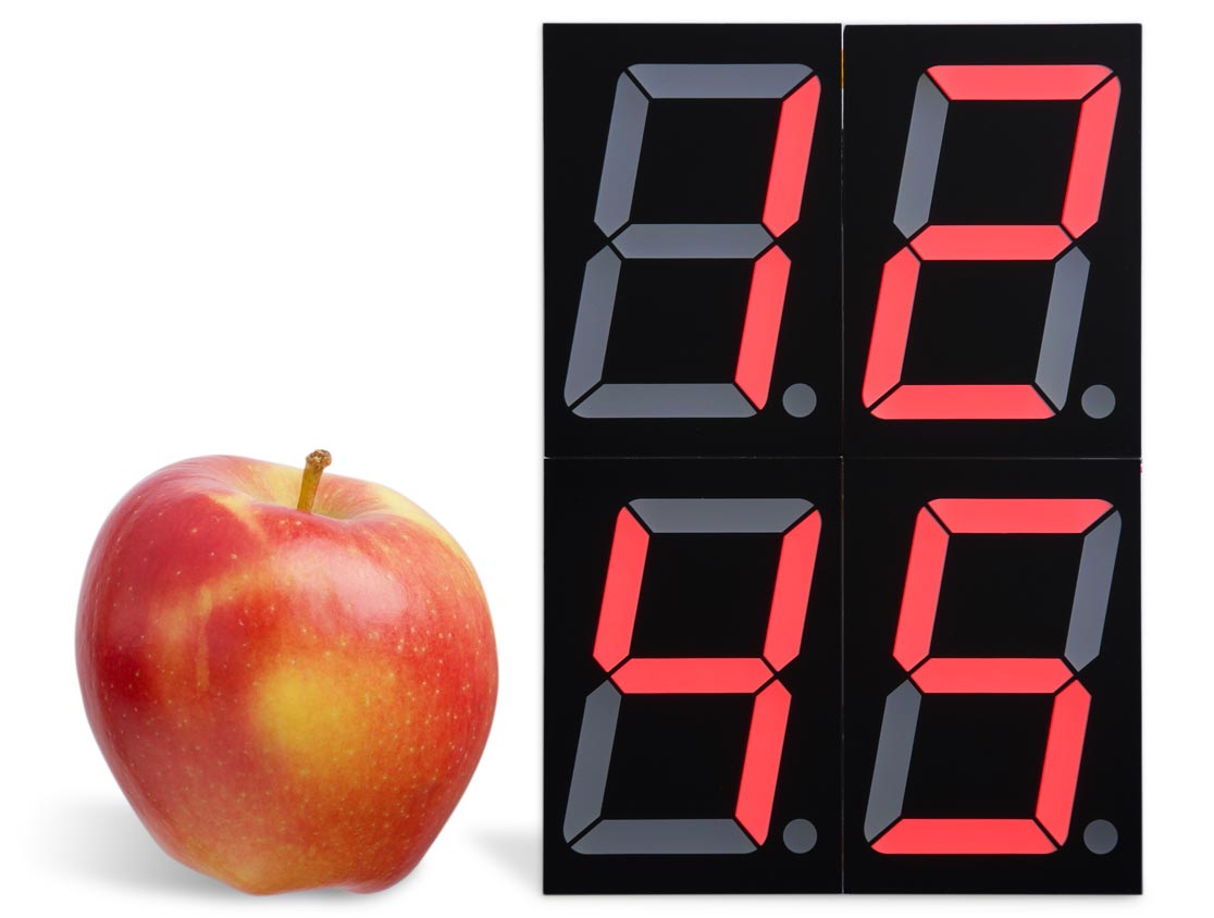
The Big Time clock, based on an ATtiny3216, uses giant 7-segment LED displays. Apple for scale.
You could also use it as the basis for a stopclock, for timing events such as sports and speedcubing.
Introduction
This clock was inspired by some 2.3" one-digit 7-segment displays I saw on AliExpress [1]. I decided it would be fun to have a clock that you can see clearly from a distance. The displays come in a variety of colours and voltages; I chose the red 4V versions so I could drive them directly from the microcontroller's I/O lines without needing driver transistors. My displays are common-cathode, but a minor change to the program would make it work with common-anode displays.
Circuit
Here's the circuit:
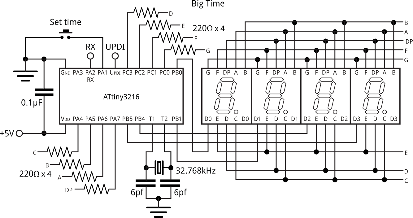
Circuit of the Big Time clock, based on an ATtiny3216.
The circuit is based on one of the new ATtiny chips which have a Real-Time Clock peripheral you can run from an external 32.768kHz crystal; see Getting Started with the New ATtiny Chips. I chose the ATtiny3216, a 20-pin member of the family with 32Kbytes of flash which has enough I/O lines to drive the displays in a straightforward way, without having to resort to charlieplexing. The program is actually small enough to fit on the 4Kbyte ATtiny416, which is otherwise equivalent.
To calculate the capacitor values I used the formula C = 2(CL - CS), where CL is the load capacitance 6pF, and CS is the stray capacitance which is usually estimated to be 2.5pF on a PCB. This gives C=7pF. I used the closest available value, 6pF.
The current-limiting resistors are in series with each segment to give consistent display brightness. A push button is provided to allow you to set the time, and I've provided access to the UPDI pin for programming the ATtiny3216, and the serial input pin, RX, in case you want to connect the clock to a GPS module; see Further suggestions below.
► Parts list
Construction
The total size of the clock display is 95mm x 140mm, which is too large to fit on a prototyping board, so I decided to design a PCB for the clock. A PCB large enough to accommodate all four displays would be expensive, so I designed the clock around three smaller PCBs which link together with two pieces of ribbon cable:
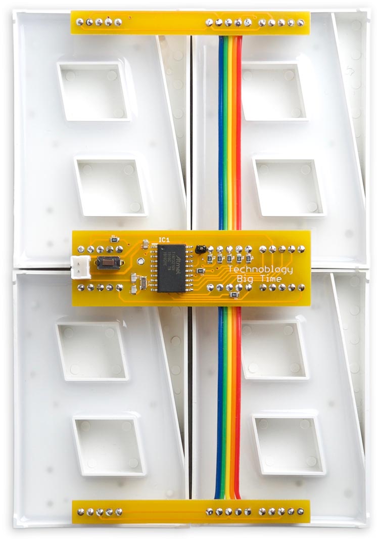
I initially designed the three PCBs as one board, with V-cuts so you could break it into three separate boards, but it turned out that it would be cheaper to make it as three separate boards, so that's how I've provided it. There are links at the end of the article if you want to order or make yourself boards.
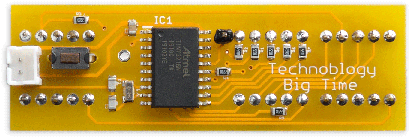
The ATtiny3216 is in an SOIC package, and the resistors and capacitor are all 0805 size, so they should be relatively easy to solder by hand. I used a Youyue 858D+ hot air gun:
The back of the main Big Time board.
I accidentally put the SMD pushbutton on the wrong side of the PCB so I had to drill two holes and use a through-hole one; I've fixed that on the final boards linked to below.
I fitted eight 5-way header sockets [2] so I could plug the displays in, but you could alternatively solder them in.
The total current consumption is about 25mA; I power the clock from a large Lipo cell that gives several days' operation.
The program
Display update
The 7-segment displays are updated from the four values in Digits[], using interrupts generated by Timer/Counter TCB. For example:
Digits[0] = 1;
Digits[1] = 2;
Digits[2] = 3;
Digits[3] = 4;
will display "1234". The display is setup by the routine DisplaySetup():
void DisplaySetup () {
  // Segment drivers
  PORTA.DIR = PIN4_bm | PIN5_bm | PIN6_bm | PIN7_bm;  // Set PA4-PA7 as outputs
  PORTC.DIR = PIN0_bm | PIN1_bm | PIN2_bm | PIN3_bm;  // Set PC0-PC3 as outputs
  // Digit drivers
  PORTB.DIR = PIN0_bm | PIN1_bm | PIN4_bm | PIN5_bm;  // Set PB0 PB1 PB4 PB5 outputs
  PORTB.OUT = PIN0_bm | PIN1_bm | PIN4_bm | PIN5_bm;  // Set PB0 PB1 PB4 PB5 high
  // Set up Timer/Counter TCB to multiplex the display
  TCB0.CCMP = 19999;                                  // Divide 5MHz by 20000 = 250Hz
  TCB0.CTRLA = TCB_CLKSEL_CLKDIV1_gc | TCB_ENABLE_bm; // Enable timer, divide by 1
  TCB0.CTRLB = 0;                                     // Periodic Interrupt Mode
  TCB0.INTCTRL = TCB_CAPT_bm;                         // Enable interrupt
}
This first makes all the segment and digit lines outputs, and takes the four digit lines PB0, PB1, PB4, and PB5 high, to turn off the digits.
Timer TCB is then set up in Periodic Interrupt Mode mode, generating an interrupt at 250Hz to multiplex the displays.
The TCB interrupt service routine simply clears the interrupt, and calls DisplayNextDigit():
ISR(TCB0_INT_vect) {
  TCB0.INTFLAGS = TCB_CAPT_bm;                        // Clear the interrupt flag
  DisplayNextDigit();
}
The current digit is stored in the global variable Digit. Each call to DisplayNextDigit() turns off the current digit, sets the segments for the next digit, and then turns that on:
void DisplayNextDigit() {
  PORTB.OUTSET = 1<<Pins[Digit];                      // Take digit high
  Digit = (Digit+1) % Ndigits;
  uint8_t segs = charArray[Digits[Digit]];
  PORTA.OUT = segs & 0xF0;                            // Set PA4-PA7
  PORTC.OUT = segs & 0x0F;                            // Set PC0-PC3
  PORTB.OUTCLR = 1<<Pins[Digit];                      // Take digit low
}
Set time button
The Set Time button allows you to set the clock to the correct time. Holding it down steps through the hours twice a second. Releasing and pressing the button again then steps through the minutes twice a second.
The button uses I/O pin PA1, and is set up with an input pullup:
void ButtonSetup () {
  PORTA.PIN1CTRL = PORT_PULLUPEN_bm;                   // PA1 input pullup
}
The button is read by ButtonDown(), which returns true if the button is being pressed:
boolean ButtonDown () {
  return (PORTA.IN & PIN1_bm) == 0;                    // True if button pressed
}
Real-Time Clock
The code to set up the RTC to use an external crystal is almost identical to my earlier project Mega Tiny Time Watch [Updated]. The real-time clock peripheral is configured as a Periodic Interrupt Timer (PIT), generating a regular interrupt. In this project the interrupt I've used a divisor of 16384, which divides down the 32.768kHz crystal to give two interrupts a second; this allows the interrupt to advance the hours or minutes twice a second when setting the time.
The interrupt service routine calculates the current time, in hours and minutes, from the global variable Time in half-seconds. If the Set Time button isn't being pressed it then increments Time, and updates the Digits[] array with the correct values:
ISR(RTC_PIT_vect) {
  int minutes, hours;
  RTC.PITINTFLAGS = RTC_PI_bm;                        // Clear interrupt flag
  minutes = (Time / 120) % 60;
  hours = (Time / 7200) % 12;
  if (ButtonDown()) {
    if (ButtonState == 1 || ButtonState == 3) {
        ButtonState = (ButtonState + 1) % 4;
    }
    if (ButtonState == 0) {                           // Advance hours
      hours = (hours + 1) % 12;
      minutes = 0;
    } else {                                          // Advance minutes
      minutes = (minutes + 1) % 60;
    }
    Time = (unsigned long)hours * 7200 + minutes * 120;
  } else {                                            // Button up
     if (ButtonState == 0 || ButtonState == 2) {
        ButtonState = (ButtonState + 1) % 4;
     }
     Time = (Time + 1) % 172800;                       // Wrap around after 24 hours
  }
  Digits[0] = (hours+1)/10;
  Digits[1] = (hours+1)%10;
  Digits[2] = minutes/10;
  Digits[3] = minutes%10;
}
Pressing the Set Time button steps the variable ButtonState between two states: 1, which advances the hours, and 3, which advances the minutes. In the intermediate states 0 and 2 the clock runs normally.
Compiling the program
Compile the program using Spence Konde's megaTiny Core on GitHub. Choose the ATtiny3216/1616/1606/816/806/416/406 option under the megaTinyCore heading on the Board menu. Check that the subsequent options are set as follows (ignore any other options):
Chip: "ATtiny3216"
Clock Speed: "5MHz"
Programmer: "jtag2updi (megaTinyCore)"
Then upload the program to the clock using a UPDI programmer. I used my UPDI Programmer Stick; alternatively you can make a UPDI programmer from an Arduino Uno, or other ATmega328P-based board, as described in Make UPDI Programmer.
You can ignore the error "Cannot locate flash and boot memories in description".
Here's the whole Big Time program: Big Time Program.
Making a PCB
Get the Eagle files for the PCBs from GitHub so you can make yourself a board, at: https://github.com/technoblogy/big-time.
Or order boards from OSH Park here: Big Time (main board), Big Time (top board), Big Time (bottom board).
Further suggestions
Although I didn't use them in my prototype, the decimal points are accessible from PA7 on the board, so you could modify the program to use them; for example, to flash them every second.
I've brought input PA2 (RX) to a terminal on the board so you could extend the clock to include a GPS module, to set the time automatically with atomic-clock accuracy. You could also use this input to start, stop, or reset a stopclock.
Updates
28th January 2025: Corrected a mistake in the #ifdef directives in the program.
13th March 2021: Added an explanation of how the crystal capacitor values are calculated.
- ^ 2.3" 7 Segment LED Display on AliExpress.
- ^ 0.1" Female Header 1x5 pin on Pololu.
blog comments powered by Disqus