Widget Dashboard
18th December 2018
This project is a dashboard for displaying the outputs from up to four different sensors or Internet of Things devices. It's based on an ATtiny85 driving an SPI 96x64 SD1331 colour OLED display:
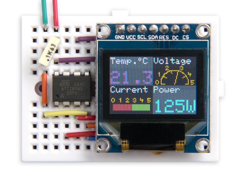
Widget Dashboard running on an ATtiny85 with a 96x64 colour OLED display.
You can include any widgets from a selection of different types, and they automatically lay themselves out on the display. You could use it for applications such as a weather station, power monitor, or circuit status display.
For a practical example of its use see ATtiny85 Weather Station [Updated].
Introduction
The Widget Dashboard runs on a low-cost 96x64 OLED display with 64K colours, and an SPI interface. It's available from a number of suppliers including Adafruit [1] or Banggood [2]. The library leaves two free pins on the ATtiny85, so you can display readings from up to four I2C sensors, or from two analogue or digital inputs.
The dashboard is based on my earlier Colour Graphics Library; for details of the circuit, and the graphics library commands, see the original article.
The widgets
The widgets use a common Frame() routine to draw the background rectangle, and the widget title:
void Frame (PGM_P title, uint8_t *x, uint8_t *y) {
  *x = (Widget%2) * 48;
  *y = 32 - (Widget/2) * 32;
  uint8_t shade;
  if (((Widget+1)/2)%2) shade = 0x04; else shade = 0x0C;
  BackR=BackG=BackB=ForeR=ForeG=ForeB=shade;
  DrawRect(1, *x, *y, (*x)+47, (*y)+31);
  ForeR=ForeG=ForeB=0x3F;
  Scale=1; MoveTo((*x)+1, (*y)+23); PlotText(title);
  Widget=(Widget+1) & 3;
}
First Frame() updates the variables pointed to by x and y to specify the origin of the new widget. DrawRect() is then called to draw a filled grey rectangle as the background for the widget. They grey is automatically chosen from two shades of grey to provide a contrasting background for adjacent widgets. Finally, the string provided in the first parameter, title, is displayed in white on the top line of the widget.
All the widgets use strings of type PGM_P, stored in program memory, to save RAM space.
Integer widget
The Integer Widget displays an integer with an optional suffix:
void IntegerWidget (PGM_P title, int value, PGM_P suffix, int colour) {
  uint8_t x0, y0;
  Frame(title, &x0, &y0);
  Scale=2;
  SetFore(colour);
  MoveTo(x0+1, y0+1);
  PlotInteger(value, suffix);
}
The fourth parameter, colour, specifies the colour of the big text. It can be one of the enums:
enum TextColour { BLACK,RED,GREEN,YELLOW,BLUE,MAGENTA,CYAN,WHITE,OLIVE,ORANGE };
The routine SetFore() sets the foreground colour to this colour.
IntegerWidget() calls the routine PlotInteger() to plot the integer with a suffix, and no leading-zeros:
void PlotInteger (int number, PGM_P suffix) {
  uint8_t len = strnlen_P(suffix, 4);
  boolean dig = false;
  unsigned int j=1000;
  for (int i=0; i<len; i++) j=j/10;
  if (number<0) { PlotChar('-'); j=j/10; }
  do {
    char c = (abs(number)/j) % 10 + '0';
    if (c == '0' && !dig && j != 1) c = ' '; else dig = true;
    PlotChar(c); j=j/10;
  } while (j);
  PlotText(suffix);
}
Number widget
The Number Widget is similar to the Integer Widget, but displays a number with one decimal place:
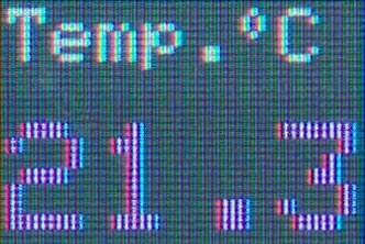
The input range is 0 to 999, with 0 displayed as "0.0" and 999 displayed as "99.9". If you're displaying the reading from an analogue input with 1024 corresponding to 5V, multiply it by 25/512 to display the voltage to the nearest 0.1V. Here's the routine:
void NumberWidget (PGM_P title, int value, int colour) {
  uint8_t x0, y0;
  Frame(title, &x0, &y0);
  Scale=2;
  SetFore(colour);
  uint8_t tens = value/100;
  MoveTo(x0+1,y0+1);
  if (tens == 0) PlotChar(' '); else PlotChar(tens+'0');
  PlotChar(value/10%10+'0');
  PlotChar('.'); PlotChar(value%10+'0');
}
Bar widget
The Bar Widget displays the value as a red bar on a green background:
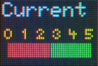
The input range is 0 to 100, with 0 corresponding to "0" on the bar, and 100 corresponding to "5". If you're displaying the reading from an analogue input multiply it by 25/256 to convert it to the correct range. Here's the routine:
void BarWidget (PGM_P title, int value) {
  uint8_t x0, y0;
  Frame(title, &x0, &y0);
  // Bar background
  BackG=ForeG=0x3F; BackR=BackB=ForeR=ForeB=0x08;
  uint8_t bar = value*4/10;
  DrawRect(1, x0+bar+4, y0+4, x0+44, y0+10);
  // Bar value
  BackR=ForeR=0x3F; BackG=BackB=ForeG=ForeB=0x08;
  DrawRect(1, x0+4, y0+4, x0+bar+4, y0+10);
  // Numbers
  ForeR=ForeG=0x3F; ForeB=0x00;
  for (int i=0; i<=5; i++) {
    MoveTo(x0+i*8+2,12+y0); PlotChar('\200'+i);
  }
}
The Bar Widget uses tiny digits, based on a 4x5 pixel matrix. These are included in the character set as characters '\200' to '\211'.
Analogue widget
The Analogue Widget displays the reading as the position of a needle on an analogue-style dial:
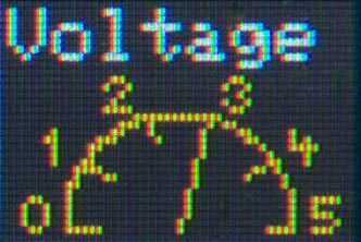
As with the Bar Widget the input range is 0 to 100, with 0 corresponding to "0" on the dial, and 100 corresponding to "5". If you're displaying the reading from an analogue input multiply it by 25/256 to convert it to the correct range. Here's the routine:
void AnalogueWidget (PGM_P title, int value) {
  uint8_t x0, y0;
  Frame(title, &x0, &y0);
  ForeR=0x3F; ForeG=0x3F; ForeB=0x00;  // Yellow
  const int Delta = 16;
  int x = -(15<<9), y = 0;
  for (int i = 0; i<=100; i++) {
    MoveTo((x>>9)+24+x0, (y>>9)+1+y0);
    x = x + ((y>>9) * Delta);
    y = y - ((x>>9) * Delta);
    DrawTo((x>>9)+24+x0, (y>>9)+1+y0);
    if (i == value) {
      MoveTo((x>>9)+24+x0, (y>>9)+1+y0);
      DrawTo(24+x0, 1+y0);
    }
    if (i%20 == 0) {
      MoveTo((x>>9)+24+x0, (y>>9)+1+y0);
      DrawTo((x>>9)-(x>>11)+24+x0, (y>>9)-(y>>11)+1+y0);
    }
  }
  // Plot tiny digits 0 to 5
  MoveTo(3+x0,0+y0); PlotChar(Tiny+0);
  MoveTo(5+x0,9+y0); PlotChar(Tiny+1);
  MoveTo(14+x0,16+y0); PlotChar(Tiny+2);
  MoveTo(30+x0,16+y0); PlotChar(Tiny+3);
  MoveTo(39+x0,9+y0); PlotChar(Tiny+4);
  MoveTo(42+x0,0+y0); PlotChar(Tiny+5);
}
The Analogue Widget uses the Minsky circle algorithm to draw each point on the semicircle from the previous point without needing floating point or trig functions. The values of x and y are calculated using fixed-point arithmetic by storing them multiplied by a factor of 2^9. The value Delta, 16, is a close approximation to π/100 * 2^9, where π is the number of radians in a semicircle, and 100 is the number of subdivisions of the semicircle we're using.
Like the Bar Widget, the Analogue Widget use tiny digits to label the dial.
Using the widgets
To use the widgets you simply put the selection of widgets you want to use in loop() in the appropriate order. Here's the arrangement I used to create the screen for this article:
void loop () {
NumberWidget(PSTR("Temp.\212C"), 213, MAGENTA);
AnalogueWidget(PSTR("Voltage"), 60);
BarWidget(PSTR("Current"), 50);
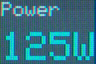
IntegerWidget(PSTR("Power"), 125, PSTR("W"), CYAN);
delay(10000);
}
It uses a degree symbol included in the character set as character '\212'.
Compiling the program
I compiled the program using Spence Konde's ATTiny Core [3]. Choose the ATtiny25/45/85 option under the ATtinyCore heading on the Board menu. Then choose Timer 1 Clock: CPU, B.O.D. Disabled, ATtiny85, 8 MHz (internal) from the subsequent menus. Choose Burn Bootloader to set the fuses appropriately. Then upload the program using ISP (in-system programming); I used Sparkfun's Tiny AVR Programmer Board; see ATtiny-Based Beginner's Kit.
Here's the Widget Dashboard program, incorporating the Colour Graphics Library it uses: Widget Dashboard Program.
Update
21st December 2018: Improved some of the explanations of the widget code snippets.
- ^ OLED Breakout Board 16-bit Color 0.96" on Adafruit
- ^ Geekcreit 0.95 inch 7 pin full colour SSD1331 SPI OLED display on Banggood.
- ^ ATTinyCore on GitHub.
blog comments powered by Disqus