ATtiny85 Analogue Clock
27th August 2014
This post describes an animated clock I designed with the hour, minute, and second shown on a traditional analogue display. It is based on the Sharp 96 x 96 LCD memory display, a low-cost graphic display with a square aspect ratio that is ideal for a clock, and its unusual mirror display is clearly visible in daylight [1]:
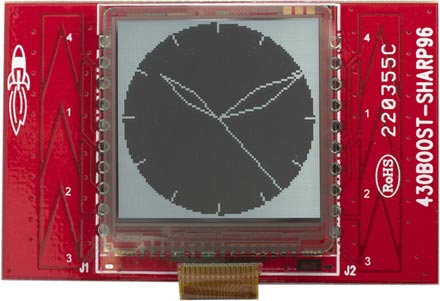
ATtiny85 Analogue Clock using the Sharp 96 x 96 LCD Memory Display.
You can't address individual pixels of the display; according to the description on the Adafruit site "the entire 96x96 bits (1,152 bytes) must be buffered by the microcontroller driver" which appears to rule out its use with an ATtiny chip, most of which have a maximum of 512 bytes of RAM [2]. This sounded like a challenge, so I set out to drive my clock using the diminuitive 8-pin ATtiny85. You could alternatively drive it from just about any other ATtiny chip, or an Arduino board.
Circuit
Adafruit make a really nicely designed breakout board for the display [3] which solves the problem of connecting to the display, and provides logic-level conversion from 5V to the display's 3V, but it's double the price of the display (the bare displays cost about £12/$20 from Mouser). I found a much cheaper alternative: the LCD BoosterPack in TI's MSP430 Launchpad series, which is £16 in the UK [4] or $20 in the USA [5], and that's what I used for this project.
I interfaced the display to an ATtiny85, using three of the five I/O pins to control the display via the SPI interface. To provide accurate time I generated the clock from an external 8MHz crystal, which used the two remaining I/O pins.
Unlike the Adafruit board, the MSP430 Launchpad board doesn't provide logic-level conversion (as the MSP430 is a 3V device), so I added an LE33CZ 3.3V regulator and a 74HC4050 Hex Non-Inverting Buffer. If you are powering the clock from a 3V battery you could omit these.
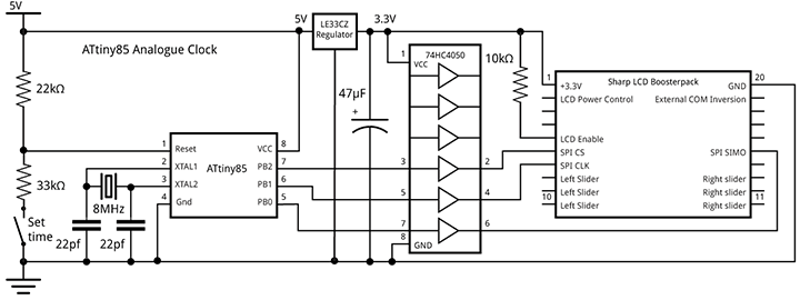
ATtiny85 Analogue Clock circuit.
The push-button allows you to set the time. It is connected to the Reset pin defined as an analogue input, using the technique described in my earlier post: Getting Extra Pins on ATtiny.
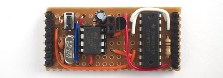
I built the circuit on a piece of Veroboard, designed to plug onto the connectors on the back of the LCD BoosterPack. It's powered by a rechargeable Lipo cell.
Approach
Each pixel on the display has a 1-bit memory, so the display retains what you've written to it. You update the display via an SPI interface, and commands are available to write a single line, update multiple lines, clear the whole display, or enter a power-saving mode [6]. To create the analogue clock face I wrote a routine that takes the current time, and draws the clock outline and hands using line-drawing commands.
I first experimented with using a memory buffer for only one line, which needs 96 bits or just 12 bytes. The point plotting routine wrote into the buffer only if it's plotting the current line. I then drew the entire clock face 96 times, once for each buffer line. Although this sounds wasteful, there's no need to update the clock more than once a second, so the only constraint is whether I can draw the clock face and output the line to the display 96 times within one second.
Using this approach I found that with an 8MHz crystal clock it took over 3 seconds to refresh the display, so I needed to speed things up by at least a factor of three.
16-line buffer
The solution was to provide a 16-line buffer, requiring a total of 192 bytes which is still well within the 512 bytes of the ATtiny85. The clock is drawn six times, once for each 16-line slice of the display. This reduced the time to update the entire display to 750ms, giving us 250ms spare to play with.
Here is the code that checks whether PlotPoint() is drawing into the current slice, and then sets the appropriate bit in the 16-line buffer:
// Screen buffer - only stores 16 lines
int Slice;
unsigned char Buffer[12][16];

// Plot point x,y (in range -48 to 47) into buffer if in current slice
void PlotPoint(int x, int y) {
  int row = 47 - y;
  int col = x + 48;
  // Set correct bit in slice buffer
  if ((row>>4) == Slice) Buffer[col>>3][row & 0x0F] |= 1<<(col & 0x07);
}
Drawing the clock
The routine to draw the clock face and hand positions uses several tricks to avoid the need for trigonometric functions, and to minimise the number of multiplications and divisions needed. The routine essentially executes the following iterative routine 360 times to generate the points on a circle
x = x + d * y;
y = y - d * x;
where d is 1 degree in radians. The values of x and y are calculated using fixed-point arithmetic by storing them multiplied by a factor of 2^9.
// Draw clock
void DrawClock(int hour, int minute, int second) {
  int x = 0;
  int y = 46<<9;
  int lasty9 = 0;
  for (int i=0; i<360; i++) {
    int x9 = x>>9;
    int y9 = y>>9;
    // Hour marks
    if (i%30 == 0) {
      MoveTo(x9 - (x9>>3), y9 - (y9>>3));
      DrawTo(x9, y9);
    }
    // Hour hand
    if (i == hour * 30 + (minute>>1))
      DrawHand(x9 - (x9>>2), y9 - (y9>>2));
    // Minute hand
    if (i == minute * 6 + second/10) DrawHand(x9, y9);
    // Second hand
    if (i == second * 6) {
      MoveTo(0, 0);
      DrawTo(x9, y9);
    }
    // Border of clock
    MoveTo(x9, y9);
    if (x9 > 0) DrawTo(47, y9); else DrawTo (-47, y9);
    x = x + (y9 * Delta);
    y = y - ((x>>9) * Delta);
  }
}
It calls DrawHand() to draw the diamond-shaped hour and minute hands:
// Draw a hand from 0,0 to x,y
void DrawHand(int x, int y) {
   int v = x/2;
   int u = y/2;
   int w = v/5;
   int t = u/5;
   MoveTo(0, 0);
   DrawTo(v-t, u+w);
   DrawTo(x, y);
   DrawTo(v+t, u-w);
   DrawTo(0, 0);
}
The line plotting is performed by the DrawTo() line-drawing routine, which uses Bresenham's line algorithm to draw the best line between two points without needing any divisions or multiplications [7]
// Draw a line to x1,y1
void DrawTo(int x1, int y1) {
  int sx, sy, e2, err;
  int dx = abs(x1 - x0);
  int dy = abs(y1 - y0);
  if (x0 < x1) sx = 1; else sx = -1;
  if (y0 < y1) sy = 1; else sy = -1;
  err = dx - dy;
  for (;;) {
    PlotPoint(x0, y0);
    if (x0==x1 && y0==y1) return;
    e2 = err<<1;
    if (e2 > -dy) {
      err = err - dy;
      x0 = x0 + sx;
    }
    if (e2 < dx) {
      err = err + dx;
      y0 = y0 + sy;
    }
  }
}
Updating the display
I updated the display using the display's Data Update Mode (Multiple Lines). The Update() procedure sends data to the display using a software implementation of SPI using three pins on the ATtiny85 to connect to the display: Ss (chip select), Clk (clock), and Mosi (serial in). This calls SendByte() to send each byte:
const int BytesPerLine = 12;
const int LinesPerSlice = 16;
const int Slices = 96 / LinesPerSlice;

// Update the display
void Update (int hour, int minute, int second) {
  digitalWrite(Ss, HIGH);
  // Command - toggle COM every second
  SendByte(0x01 | (second & 0x01)<<1);
  for (Slice=0; Slice < Slices; Slice++) {
    // Clear buffer
    for (int i=0; i<BytesPerLine; i++)
      for (int j=0; j<LinesPerSlice; j++)
        Buffer[i][j] = 0;
    // Draw clock for this slice
    DrawClock(hour, minute, second);
    int SliceStart = Slice<<4;
    for (int j=0; j<LinesPerSlice; j++) {
      // Send line address
      SendByte(SliceStart + j + 1);
      // Send line data
      for (int i=0; i<BytesPerLine; i++)
        SendByte(Buffer[i][j]);
      // Send dummy bits
      SendByte(0);
    }
  }
  SendByte(0);
  digitalWrite(Ss, LOW);
}
Whether or not you're writing data to the display, you also need to refresh the display by toggling a signal called COM at a rate of between 1 and 60Hz; there's a good explanation of this on Richard Leszczynski's MakerDyne site [8]. You can either do this by providing an external signal, called EXTCOMIN, or in software by toggling bit 1 in the command byte at the start of the display data. In the above routine I used the software approach, using the bottom bit of the number of the second to refresh the display at 1Hz.
Calculating the time
Finally, the clock keeps time using the Arduino library millis() function, using the accuracy of the 8MHz crystal to give a reasonable level of accuracy:
void loop() {
  unsigned long Start = millis();
  int Second = Time % 60;
  int Minute = (Time / 60) % 60;
  int Hour = (Time / 3600) % 12;
  Update(Hour, Minute, Second);
  // Read set-time button
  if (analogRead(A0) < 900) {
    Time = ((Time / 60) + Factor) * 60;
    Factor = Factor + 1;
  } else {
    Factor = 0;
    Start = Start + 1000;
    Time = Time + 1;
    // Wait until the end of this second
    do ; while (millis() < Start);
  }
}
Holding the push-button down initially increases the speed of the clock by a factor of 60, and this increases every second.
Compiling the program
I compiled the program using the ATtiny core extension to the Arduino IDE [9]. This doesn't include a setting for the ATtiny85 with an 8MHz crystal, so I added the following definition to the boards.txt file:
###########################################################################

attiny85at8x.name=ATtiny85 @ 8 MHz  (external crystal; BOD disabled)

attiny85at8x.upload.using=arduino:arduinoisp
attiny85at8x.upload.maximum_size=8192

# Ext. Crystal Osc. 8 MHz; Start-up time: 16K CK/14 CK + 65 ms; [CKSEL=1111 SUT=11]
# Brown-out detection disabled; [BODLEVEL=111]
# Preserve EEPROM memory through the Chip Erase cycle; [EESAVE=0]
# Serial program downloading (SPI) enabled; [SPIEN=0]

attiny85at8x.bootloader.low_fuses=0xFF
attiny85at8x.bootloader.high_fuses=0xD7
attiny85at8x.bootloader.extended_fuses=0xFF
attiny85at8x.bootloader.path=empty
attiny85at8x.bootloader.file=empty85at16.hex

attiny85at8x.build.mcu=attiny85
attiny85at8x.build.f_cpu=8000000L
attiny85at8x.build.core=tiny

###########################################################################
This adds an ATtiny85 @ 8MHz (external crystal; BOD disabled) option to the Board submenu. Select this, and choose Burn Bootloader to set the fuses appropriately using the Tiny AVR Programmer Board; see ATtiny-Based Beginner's Kit. Then upload the program to the ATtiny85.
You can get the full listing here: Analogue Clock Program.
Other options
For greater accuracy you could use an RTC module, such as the SparkFun DeadOn RTC DS3234 Breakout [10], available in the UK from Proto-PIC [11]. Alternatively you could drive it from a radio time code module as in my earlier application: Radio Time Code Clock. In either case this would allow you to use the ATtiny85's internal 8MHz clock, freeing up two I/O pins.
It would also be possible to display other information on the clock face, such as the date or temperature.
- ^ SHARP Memory Display Breakout on Adafruit.
- ^ Atmel AVR ATtiny comparison chart on Wikipedia.
- ^ SHARP Memory Display Breakout on Adafruit.
- ^ LCD BoosterPack on Farnell.
- ^ LCD BoosterPack on Newark.
- ^ Sharp LS013B4DN04 Datasheet on Adafruit (PDF).
- ^ Bresenham's line algorithm on Wikipedia.
- ^ Small Memory LCD Breakout Board Details on MakerDyne.
- ^ ATtiny core for Arduino: arduino-tiny on Google Code.
- ^ DeadOn RTC - DS3234 Breakout on SparkFun.
- ^ DeadOn RTC - DS3234 Breakout on Proto-PIC.
blog comments powered by Disqus