ATtiny10 Thermometer
24th January 2019
This is a small battery-powered thermometer that displays the temperature as a series of red and green flashes on an LED:
ATtiny10-based thermometer, flashes the temperature on a bi-colour LED.
The thermometer consists of an ATtiny10, a DS18B20 1-wire temperature sensor, and a bi-colour LED. To avoid the need for a digital display, and minimise current consumption, the thermometer pulses the temperature as a series of red or green flashes on the bi-colour LED. I designed it so I could seal it in a small waterproof enclosure and put it outside the window, allowing me to see the outdoor temperature from inside.
It incorporates several power-saving features to enable it to run for over a year on a CR2032 button cell.
For a PCB version of this project see ATtiny10 Thermometer PCB.
Introduction
Some time ago I designed a flashing thermometer based on an ATtiny85, using the ATtiny85's internal tempreature sensor: Flashing Thermometer.
Despite its elegant simplicity the circuit wasn't very accurate, because of the limitations of the internal temperature sensor. I recently wanted to build another thermometer, and decided this time to base it on a DS18B20 1-wire temperature sensor that has an accuracy of 0.5°C and doesn't require calibration. I decided to use an ATtiny10 for the processing, so I could eventually make a version with SMD components on a PCB the same size as a button cell. For this prototype I used through-hole components and an ATtiny10 on a breakout board.
The original flashing thermometer displayed the temperature in a little-known notation called negabinary. This time I've also supported an alternative notation I've called Easy Binary that you may find more intuitive than negabinary. In each case it flashes the digits starting with the most significant digit, with red representing a one and green a zero.
Easy Binary
Easy Binary notation is designed to be easy to convert in your head, and avoids the need to understand twos-complement signed binary notation for negative temperatures. It works as follows:
- Positive temperatures are given in binary, with no leading zeros.
- Zero is given as one zero.
- Negative temperatures are given as one zero followed by the binary for the positive number.
The lowest recorded temperature in the UK was -27°C (Altnaharra, December 1995), and the highest was 38°C (Kent, August 2003). As an example, here are the sequences of flashes for these two extreme UK temperatures and 0°C:
Three temperatures represented as a series of flashes in "Easy Binary" notation.
Converting from Easy Binary
Here's an easy way of converting a number from Easy Binary to decimal:
Keep a running total; initially the total is 0. Then, for each flash:
- Multiply your total by 2.
- Add the value of the flash (green=0 or red=1) to your total.
When there are no more flashes your total is the decimal value of the number, or minus that number if the first flash was green.
Negabinary
Negabinary notation which is ideal for this application, and gives a very compact way of expressing the temperature. If you know binary you should find it easy to understand.
To understand negabinary, first consider how binary represents numbers using the digits 0 and 1. Each bit represents the power of two corresponding to its position; so, for example, the binary number 1101011 represents 107, because 64 + 32 + 8 + 2 + 1 = 107:
Negabinary is similar, except that it uses the powers of -2 rather than the powers of 2. So each bit represents the power of -2 corresponding to its position.
In negabinary the same number 1101011 represents 23 because 64 - 32 - 8 - 2 + 1 = 23:
So what's the point of negabinary? Its advantage over binary is that it can represent both positive and negative numbers in a consistent, compact way. This is exactly what we want for temperatures, because the temperatures we are measuring tend to be either side of zero.
For example, here are the sequences of flashes for the two extreme UK temperatures, 38°C and -27°C, and 0°C:
Three temperatures represented as a series of flashes in negabinary notation.
Converting from negabinary
Here's an easy way of converting a number from negabinary to decimal:
Keep a running total; initially the total is 0. Then repeat this for each flash:
- Multiply your total by -2.
- Add the value of the flash (green=0 or red=1) to your total.
When there are no more flashes your total is the decimal value of the number.
The circuit
Here's the circuit of the flashing thermometer:
Circuit of the flashing thermometer.
The circuit is based on a DS12B20 [1] temperature sensor in a TO-92 transistor package, which has a supply range of 3.0V to 5.5V; you can also find them very cheaply on Chinese sites. The MAX31820 [2] is equivalent and cheaper, but has a maximum supply voltage of 3.7V.
The ATtiny10 is in an SOT-23 package, so I mounted it on a small breakout board [3].
For the LED I chose an ultra-bright red/green bicolour LED from Kingbright, which is still clearly visible with a very short pulse duration [4]. Alternatively you could use separate red and green LEDs.
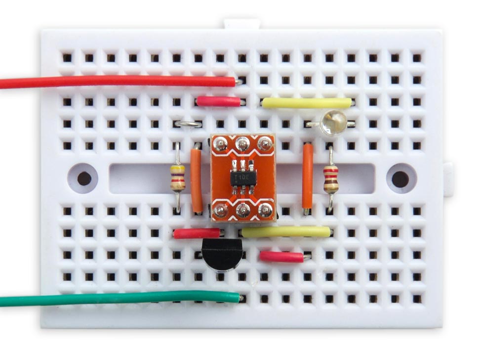
I built the circuit on a mini breadboard, available from SparkFun [5] or HobbyTronics in the UK [6].
The program
Reading the temperature sensor
The 1-wire interface to the temperature sensor is based on my earlier Simple 1-Wire Interface, using the ATtiny10’s 16-bit Timer/Counter0 to do the timing. It is set up with a 1MHz clock:
uint8_t OneWireSetup () {
  TCCR0A = 0<<WGM00;                // Normal mode
  TCCR0B = 0<<WGM02 | 2<<CS00;      // Normal mode; 1MHz clock
 }
The routine DelayMicros() then gives a delay in a specified number of microseconds by waiting for a compare match with output compare register OCR0A:
void DelayMicros (unsigned int micro) {
  TCNT0 = 0; TIFR0 = 1<<OCF0A;
  OCR0A = micro;
  while ((TIFR0 & 1<<OCF0A) == 0);
}
Since there is only one device on the bus you can ignore the serial number, and just send a Skip ROM command which sends subsequent commands to any device.
The DS12B20 or MAX31820 returns the temperature as a signed 16-bit integer in units of 1/16th of a degree.
Displaying the number as flashes
Here's the routine to display a binary number as a series of red or green flashes:
void Flash (unsigned int value) {
  int b, zeros = false;
  for (int i=7; i>=0; i--) {
    b = value>>i & 1;
    if (zeros || b || (i==0)) {
      if (value>>i & 1) Pulse(RedPin); else Pulse(GreenPin);
      zeros = true;
    }
  }
}
It uses the variable zeros to suppress leading zeros unless the number is zero, in which case it gives a single green flash.
Errors
If the 1-wire interface fails to find a 1-wire device on the bus it gives a 1 second red flash.
If the 1-wire interface gets a CRC error in the data read from the temperature sensor it gives a 1 second green flash.
Converting to negabinary
The program uses the following ingenious routine to convert the temperature from a signed integer to an unsigned integer representing the negabinary result:
unsigned int NegaBinary (unsigned int value) {
  return (value + 0xAAAAAAAA) ^ 0xAAAAAAAA;
}
The way this works is quite obscure; there's an explanation in Hacker's Delight [7].
Power saving features
The thermometer uses the following power-saving features to ensure that it will last as long as possible on a single battery.
LED flashes
Most of the power is consumed by the LED. I chose a high brightness two-colour LED so it would be visible even with very short pulse durations - it's only on for 12msec, but is still clearly visible.
Power down
Whenever the thermometer is not measuring or displaying the temperature it puts the ATtiny10 to sleep, reducing the power consumption to 5.5µA. The processor sleeps for 16 seconds between each display of temperature, and for 1 second between each flash. In each case the processor is woken from sleep using the watchdog timer, which generates a watchdog timer interrupt after a specified delay.
Here's the routine to use the watchdog timer for a delay:
void WDDelay (int n) {
  set_sleep_mode(SLEEP_MODE_PWR_DOWN);
  WDTCSR = 1<<WDIE | (n & 0x8)<<2 | (n & 0x7);
  sleep_enable();
  sleep_cpu();
}
This enables the watchdog timer, and the parameter n sets the watchdog timer prescaler. A value of 0 gives a 16 millisecond delay, a value of 6 gives a 1 second delay and a value of 9 gives an 8 second delay.
The watchdog interrupt service routine simply disables the watchdog timer:
ISR(WDT_vect) {
  WDTCSR = 0<<WDIE;
}
While asleep the current consumption is negligible (5.5µA at 3.0V). When lit the LEDs consume about 5mA, but they are only lit for about 60ms every 16s, which is a duty cycle of about 1:266. This is equivalent to a battery life of about 500 days for a CR2032 button cell with a capacity of 225mAH.
The main program
The main program sleeps for 16 seconds, and then flashes the temperature in the chosen notation.
To display the temperature in my Easy Binary notation use this routine:
void loop () {
  WDDelay(9);                       // 8 second delay
  WDDelay(9);                       // and another 8 second delay;
  int temp = Temperature();         // In sixteenths of a degree
  if (temp < 0) { Pulse(GreenPin); temp = -temp; }
  Flash(temp>>4);
}
To display the temperature in negabinary use this routine:
void loop () {
  WDDelay(9);                       // 8 second delay
  WDDelay(9);                       // and another 8 second delay;
  int temp = Temperature();         // In sixteenths of a degree
  Flash(Negabinary(temp>>4));
}
The whole program takes 774 bytes, so it easily fits in the 1024 byte flash memory of the ATtiny10.
Compiling the program
I compiled the program using the ATtiny10Core which you can download from my ATtiny10Core repository on GitHub. Select the ATtiny10/9/5/4 option under the ATtiny10Core heading on the Boards menu. Then choose ATtiny10 from the Chip menu.
I uploaded the program to the board using the USBasp programmer. For more details about the procedure see my earlier article Programming the ATtiny10 [Updated].
Note: You need to remove the temperature sensor from the circuit while uploading to the ATtiny10 as it interferes with the upload process.
Here's the whole ATtiny10 Thermometer program: ATtiny10 Thermometer Program.
Updates
27th July 2019: Corrected a mistake in the circuit diagram.
7th March 2021: Updated the program for compatibility with the latest version of my ATtiny10Core.
- ^ One Wire Digital Temperature Sensor - DS18B20 on Sparkfun
- ^ One-Wire Ambient Temperature Sensor - MAX31820 on Sparkfun
- ^ 6 pin SOT-23 to DIP Adapter PCB on eBay.
- ^ Kingbright L-93WSURKCGKC LED on Farnell.
- ^ Breadboard - Mini Modular on SparkFun.
- ^ Mini Breadboard from HobbyTronics.
- ^ Warren Jr., Henry S. (2013) [2002]. Hacker's Delight (2 ed.). Addison Wesley - Pearson Education, Inc., p. 305-306.
blog comments powered by Disqus