Tiny I2C Routines for all AVR Microcontrollers
19th April 2022
This article describes a set of minimal I2C routines that allow just about any Microchip/Atmel AVR processor to connect to I2C peripherals. To demonstrate the routines I've designed a port scanner that displays the I2C address of a sensor on a dot-matrix display, and a digital thermometer that reads the temperature from an I2C temperature sensor and displays it:
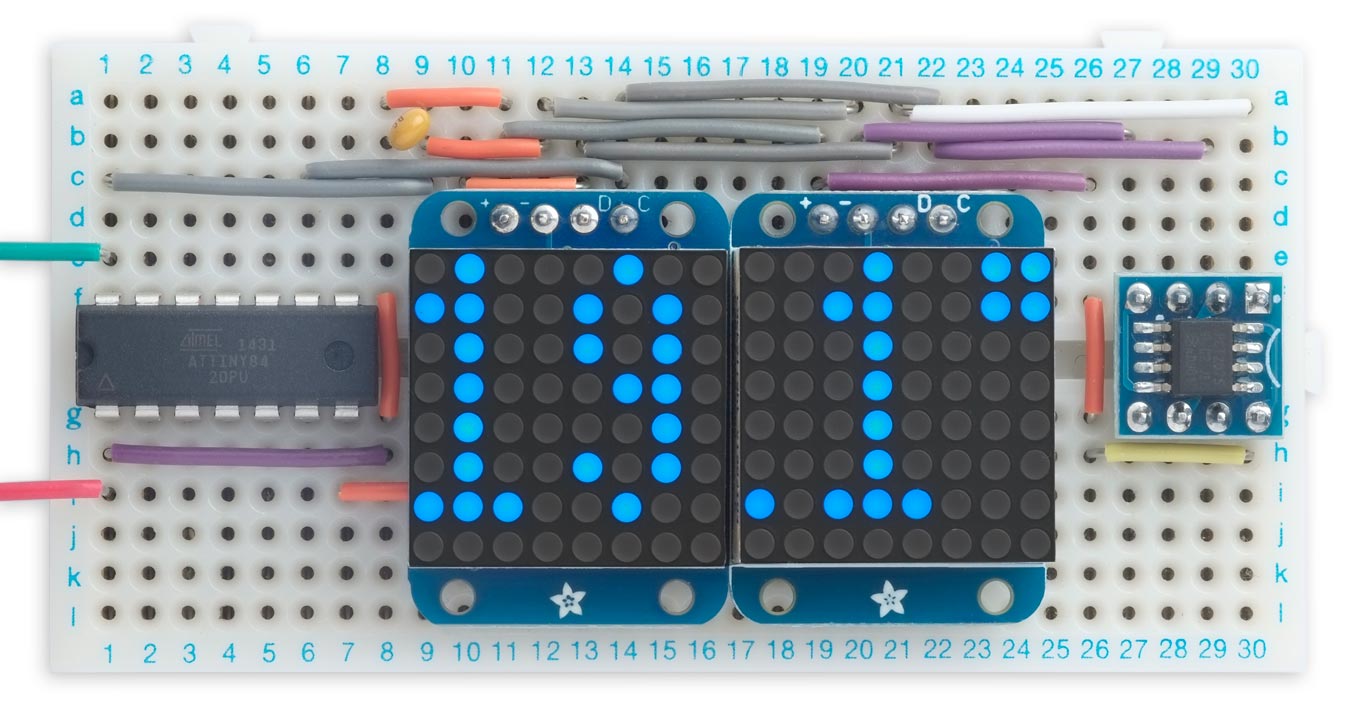
A simple Dot-Matrix Thermometer based on an ATtiny84 using these TinyI2C routines.
The main difference between these routines and the standard Arduino Wire library is that these don't need to use buffers, so have much smaller memory requirements and don't impose a limit on transmissions.
Compatibility
These I2C routines are designed to provide master I2C functionality for all Microchip/Atmel AVR processors. Over the years different generations of AVR chips have featured three different, incompatible peripherals to handle I2C:
Universal Serial interface (USI) peripheral
The USI provides master I2C support to ATtiny processors with a USI peripheral, namely:
- ATtiny25/45/85 and ATtiny24/44/84
- ATtiny261/461/861
- ATtiny87/167
- ATtiny2313/4313
- ATtiny1634
The routines to support the USI are based on the code described by Atmel Application Note AVR310 [1].
2-Wire Serial Interface (TWI) peripheral
This provides full master I2C support, and is featured in:
- Most of the original ATmega processors, such as the ATmega328P used in the Arduino Uno, ATmega2560 used in the Arduino Mega 2560, and the ATmega1284P.
- Two unusual ATtiny processors that provide a TWI peripheral, the ATtiny48 and 88.
Two-Wire Interface (TWI) peripheral
A new version of the TWI peripheral is featured in:
- The latest ATtiny 0-series, 1-series, and 2-series processors, such as the ATtiny414.
- The 0-series ATmega chips, such as the ATmega4809.
- The AVR DA and DB family, such as the AVR128DA48.
Universal TinyI2C routines
These universal Tiny I2C routines provide master I2C support for all three generations of AVR processors by providing three separate blocks of code. The correct block of code is selected automatically by #if defined statements depending on which Arduino core and Board setting you are using.
Although I've tested these routines on selected processors from each category I haven't exhaustively tested every AVR processor. Please report any incompatibilities on GitHub.
These routines incorporate, and supersede, the two earlier versions of my minimal I2C routines:
- Minimal Tiny I2C Routines (TinyI2C) for ATtiny processors with a USI peripheral, such as the ATtiny85.
- Minimal I2C for the New AVR Microcontrollers (TinyMegaI2C) for the new 0-series and 1-series ATtiny and ATmega microcontrollers, such as the ATtiny402 or ATmega4809.
Differences from Arduino Wire
I've named these routines TinyI2C for two reasons: to distinguish them from the existing TinyWire libraries, such as the ones included in the Arduino and Spence Konde's cores, and to emphasise that these routines don't follow the Arduino Wire library naming conventions.
In addition, these routines differ from the Arduino Wire library routines in the following ways:
Low memory requirements
These routines don't need to use buffers, reducing their RAM requirements to a couple of bytes. The standard Arduino Wire library uses 128-byte or 32-byte send and receive buffers. As far as I can see there's no need for buffering as the I2C protocol incorporates handshaking, using the ACK/NACK pulses.
Unlimited transmission length
These routines don't impose any limit on the length of transmissions. The standard Wire libraries limit the length of any transmission to the size of the buffer. This isn't a problem with many I2C applications, such as reading the temperature from a sensor, but it is a problem with applications such as driving an I2C OLED display, which requires you to send 1024 bytes to update the whole display.
Flexible read
These routines allow you to specify in advance how many bytes you want to read from an I2C peripheral, or you can leave this open-ended and mark the last byte read. This is an advantage when you don't know in advance how many bytes you are going to want to read.
Polling
For simplicity these routines use polling rather than interrupts, so they won't interfere with other processes using interrupts.
Performance
I've tested these routines on a selection of platforms, and the following table compares the total program memory (flash) and dynamic memory (RAM) usage, in bytes, of the TinyI2C and Arduino Wire versions of the Dot Matrix Thermometer application, as reported by the Arduino IDE:
| TinyI2C | Arduino Wire | ||||
| Processor | Arduino core | Program memory | RAM | Program memory | RAM |
| ATtiny84 | ATTinyCore | 1340 | 11 | 2074 | 50 |
| ATtiny85 | ATTinyCore | 1366 | 11 | 2086 | 50 |
| ATtiny88 | ATTinyCore | 1522 | 11 | 2798 | 213 |
| ATmega328P | Arduino AVR Boards | 1808 | 11 | 3916 | 225 |
| ATmega1284P | MightyCore | 2168 | 11 | 3896 | 223 |
| ATtiny414 | megaTinyCore | 1434 | 12 | 2260 | 98 |
| ATmega4809 | MegaCoreX | 1664 | 6 | 2644 | 306 |
| AVR128DA28 | DxCore | 1909 | 6 | 3987 | 311 |
Depending on the platform, the TinyI2C code is typically about half the size of the Arduino Wire code, with 5% of the RAM usage.
Description
Get the TinyI2C Library from GitHub here: TinyI2C Library.
Install it into your libraries folder in your Arduino folder and include this at the top of your program:
#include <TinyI2CMaster.h>
Here's a description of the minimal TinyI2C routines:
TinyI2C.init()
Initialises TinyI2C. This should be called in setup().
TinyI2C.start(address, type)
Starts a transaction with the slave device at the specified address, and specifies if the transaction is going to be a read or a write. It returns true if the start was successful or false if there was an error.
The type parameter can have the following values:
- 0: Write to the device.
- 1 to 32767: Read from the device. The number specifies how many bytes you are going to read.
- -1: Read an unspecified number of bytes from the device.
If type is specified as -1 you must identify the last byte read by calling TinyI2C.readlast() rather than TinyI2C.read().
TinyI2C.write(data)
Writes a byte of data to a slave device. It returns true if the write was successful or false if there was an error.
TinyI2C.read()
Reads a byte from a slave device and returns it.
TinyI2C.readLast()
Reads a byte from a slave device and tells the slave to stop sending.
You only need to use TinyI2C.readlast() if you called TinyI2C.start() or TinyI2C.restart() with type set to -1.
TinyI2C.restart(address, type);
Does a restart. The type parameter is the same as for TinyI2C.start().
TinyI2C.stop()
Ends the transaction; there's no return value.
Every TinyI2C.start() should have a matching TinyI2C.stop().
Using the TinyI2C library
Pullup resistors
You must have pullup resistors on the SCL and SDA lines for I2C to work reliably; recommended values are 4.7kΩ or 10kΩ. On platforms where this is possible the TinyI2C routines turn on the internal pullups on the SCL and SDA lines as this can't do any harm, but you shouldn't rely on these.
Writing to an I2C device
Writing to an I2C device is straightforward: for example, to write one byte:
TinyI2C.start(Address, 0);
TinyI2C.write(byte);
TinyI2C.stop();
Reading from an I2C device
The TinyI2C routines allow you to identify the last byte read from an I2C device in either of two ways:
You can specify the total number of bytes you are going to read, as the second parameter of TinyI2C.start(). With this approach TinyI2C.read() will automatically terminate the last call with a NAK:
TinyI2C.start(Address, 2);
int mins = TinyI2C.read();
int hrs = TinyI2C.read();
TinyI2C.stop();
Alternatively you can just specify the second parameter of TinyI2C.start() as -1, and explicitly identify the last TinyI2C.read command by calling TinyI2C.readlast():
TinyI2C.start(Address, -1);
int mins = TinyI2C.read();
int hrs = TinyI2C.readLast();
TinyI2C.stop();
Writing and reading
Many I2C devices require you to write one or more bytes before reading, to specify the register you want to read from; the read should be introduced with a TinyI2C.restart() call; for example:
TinyI2C.start(Address, 0);
TinyI2C.write(1);
TinyI2C.restart(Address, 2);
int mins = TinyI2C.read();
int hrs = TinyI2C.read();
TinyI2C.stop();
Example programs
I used two example programs to test these routines:
- An I2C port scanner that displays the address of all I2C devices on the bus as a dot on two 8x8 dot matrix displays.
- A simple digital thermometer that displays the temperature on the same two 8x8 dot matrix displays.
I chose these examples because they demonstrate both writing and reading data over I2C.
The circuit
The example programs run on the same circuit. Here's the version using the ATtiny84:
Circuit of the Dot-Matrix Thermometer based on an ATtiny84.
For the displays I used Adafruit I2C mini 8x8 dot matrix displays [2], available from The Pi-Hut in the UK [3]. They are available in a range of colours. You could also use Keyestudio I2C displays [4]. You need to set the addresses of the two displays to different values by putting a solder bridge across the A0 link on the back of one display. The dot-matrix displays include I2C pullup resistors so you don't need external ones.
The temperature is provided by a PCT2075 SOIC-8 I2C temperature sensor [5]. This is a pin-compatible replacement for the popular LM75, but with 11-bit accuracy compared to the LM75's 9-bits. Additionally, the PCT2075 allows the address pins to work in three states, allowing you to assign one of 27 different I2C addresses. With the three address lines unconnected the address is 0x37.
The programs
The dot-matrix displays are configured by InitDisplay():
void InitDisplay (int address) {
  TinyI2C.start(address, 0);
  TinyI2C.write(0x21);
  TinyI2C.restart(address, 0);
  TinyI2C.write(0x81);
  TinyI2C.restart(address, 0);
  TinyI2C.write(0xe0 + Brightness);
  TinyI2C.stop();
}
The routine ClearDisplay() clears the specified display by writing zeros to the displays:
void ClearDisplay (int address) {
  TinyI2C.start(address, 0);
  for (int i=0; i<17; i++) TinyI2C.write(0);
  TinyI2C.stop();
}
I2C Port scanner
The I2C port scanner works as follows. The displays are initially cleared. Then, as the port scanner checks each address it lights the dot corresponding to that address, where 0 is top left, 15 is top right, and 127 is bottom right. It's quite convenient that the displays provide 128 dots, the same as the number of addresses supported by I2C.
If a device is found on a particular address the dot is turned off. With the circuit above the two dots corresponding to the display addresses 0x70 and 0x71 will be indicated, in addition to the address 0x37 used by the temperature sensor:
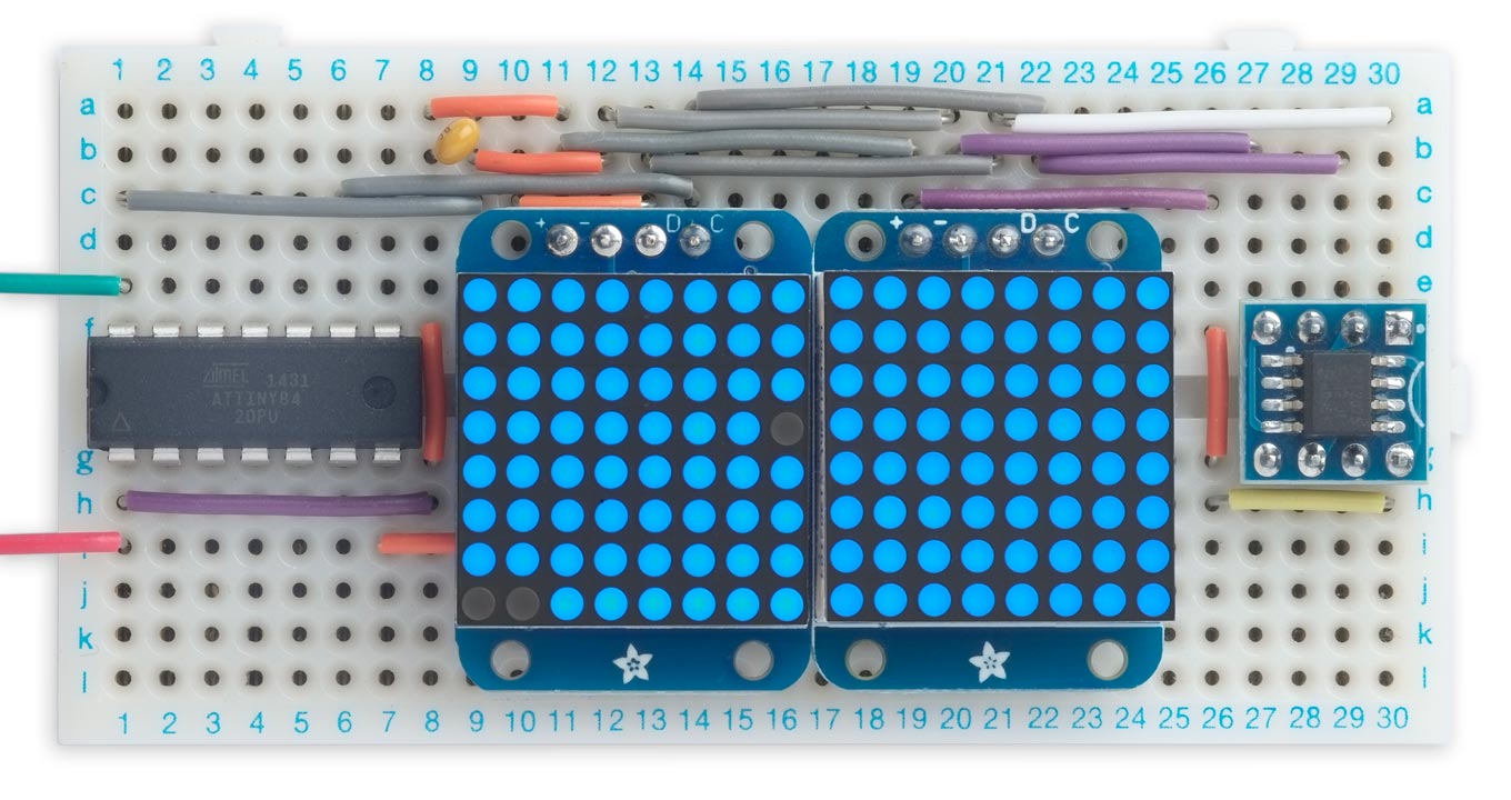
Circuit of the Dot-Matrix I2C Port Scanner based on an ATtiny84.
To check other I2C devices just connect them to the I2C bus SCL and SDA lines.
The program calls the routine Plot() to plot a pixel on the appropriate display at location (x, y), where x goes from 0 to 15, y goes from 0 to 7, and (0, 0) is top left pixel:
void Plot (int x, int y) {
  uint8_t address;
  if (x > 7) address = DisplayRight; else address = DisplayLeft;
  TinyI2C.start(address, 0);
  TinyI2C.write(y * 2);
  TinyI2C.restart(address, 1);
  uint8_t row = TinyI2C.read();
  TinyI2C.restart(address, 0);
  TinyI2C.write(y * 2);
  TinyI2C.write(row | 1<<((x + 7) & 7));
  TinyI2C.stop();
}
The scan is performed by loop():
void loop () {
  for (int p=0; p<128; p++) {
    if (!TinyI2C.start(p, 0)) Plot(p&15, p>>4);
    delay(50);
  }
  for(;;);
}
Dot-Matrix Thermometer
The Dot-Matrix Thermometer reads the temperature from the temperature sensor every second, and updates the displays to show the temperature in degrees Celsius to one decimal place.
The display uses a 3x7 pixel character set for the digits 0 to 9, defined by:
const uint32_t PROGMEM Digits [8] = {
0b010010111010111001010010010010,
0b101101100101001001101101011101,
0b101101100001001101100100010101,
0b110010010011011111010010010101,
0b100101001101100100100001010101,
0b101101001101101100101001010101,
0b010010001010010100010111111010 };
This stores the character-set definitions in program memory, to save RAM. The 32-bit words correspond to the following bitmap, which contains the 3x7 pixel digits 0 to 9 reflected right-to-left:

The routine PlotDigit() plots a digit n on a specified display with the offset x:
void PlotDigit (int address, uint8_t x, uint8_t n) {
  for (int y=0; y<7; y++) {
    TinyI2C.start(address, 0);
    TinyI2C.write(y * 2);
    TinyI2C.restart(address, 1);
    uint8_t row = TinyI2C.read();
    TinyI2C.restart(address, 0);
    TinyI2C.write(y * 2);
    uint8_t b = (pgm_read_dword(&Digits[y])>>(3*n) & 7);
    TinyI2C.write((row & ~(7<<(x - 1))) | (b<<x | b<<(8+x))>>1);
    TinyI2C.stop();
  }
}
It reads the previous state of each row, clears the three pixels at offset x, and then plots the appropriate bits from the character-set bitmap. The expression:
(b<<x | b<<(8+x))>>1
compensates for the fact that for some reason the displays are wired up so that the bits in each row are numbered 7, 0, 1, 2, 3, 4, 5, 6 from left to right.
The routine Symbols() plots the degree symbol and decimal point:
void Symbols (int address) {
 TinyI2C.start(address, 0);
 TinyI2C.write(0);
 TinyI2C.write(0x60);
 TinyI2C.write(0);
 TinyI2C.write(0x60);
 TinyI2C.restart(address, 0);
 TinyI2C.write(6*2);
 TinyI2C.write(0x80);
 TinyI2C.stop();
}
The PCT2075 temperature sensor is read by the following routine, which returns the temperature as an integer in 1/8ths of a degree Celsius:
int PCT2075Temp (int address) {
  TinyI2C.start(address, 0);
  TinyI2C.write(0);
  TinyI2C.restart(address, 2);
  uint8_t hi = TinyI2C.read();
  uint8_t lo = TinyI2C.read();
  int temp = hi<<3 | lo>>5;
  return (temp & 0x03FF) - (temp & 0x0400);
}
Finally, the temperature is read every second and plotted as three digits on the displays by loop():
void loop () {
  int temp = PCT2075Temp(ThermometerAddress);
  PlotDigit(DisplayLeft,0,temp/80);
  PlotDigit(DisplayLeft,4,temp/8 % 10);
  PlotDigit(DisplayRight,2,(temp%8 * 10 + 4)/8);
  delay(1000);
}
Running the programs
Universal Serial interface (USI) peripheral
To test the programs with the USI peripheral I used the ATtiny84, a 14-pin chip with 8K bytes of program memory and 512 bytes of RAM. I also tested it with the 8-pin ATtiny85.
On these chips you need to connect to the pins marked SDA and SCL on the datasheet. On the ATtiny85 these are PB0 and PB2 respectively.
I compiled the program using Spence Konde's ATTinyCore. Note that after uploading the program to the ATtiny84 (or ATtiny85) via ISP you need to disconnect the ISP MOSI connection to pin 7 (or pin 5) and reapply power, because the ISP circuit interferes with the SDA signal which is on the same pin.
2-Wire Serial Interface (TWI) peripheral
To test the program with the 2-Wire Serial Interface in the original ATmega chips I used an Arduino Uno connected to the prototyping board via four wires: GND, VDD, SCL, and SDA, and used the Arduino AVR Boards core.
I tested it with the ATtiny88, which has this peripheral rather than the USI in other ATtinys, using Spence Konde's ATTinyCore.
I also tested it with an ATmega1284P using MCUDude's MightyCore.
Two-Wire Interface (TWI) peripheral
To test the program with the Two-Wire Interface peripheral in the latest 0-series and 1-series of ATtiny chips I used the ATtiny414, a 14-pin processor with 4K bytes of program memory and 256 bytes of RAM:
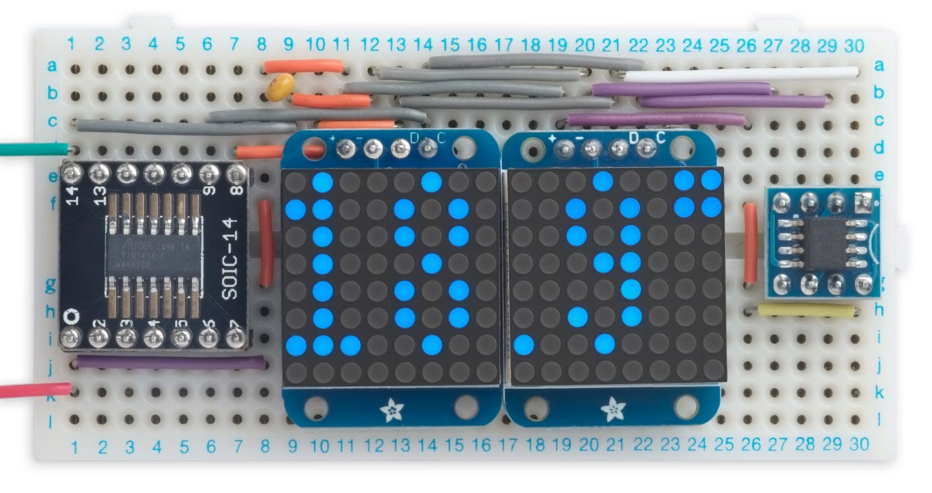
The ATtiny414 version of the Dot-Matrix Thermometer.
Here's the circuit:
Circuit of the ATtiny414 version of the Dot-Matrix Thermometer.
I compiled the program using Spence Konde's megaTiny Core, and uploaded it using a UPDI programmer.
I also tested the program with an 0-series ATmega4809 on a separate prototyping board, compiler it using MCUdude's MegaCoreX, and uploaded it to the chip via UPDI.
Finally I tested the program with an AVR128DA28 on a separate prototyping board, compiled the program using Spence Konde's DxCore, and again uploaded it to the chip via UPDI.
Resources
Here's the new universal version of the TinyI2C library on GitHub: TinyI2C Library.
Here's the Dot-Matrix I2C Port Scanner example: Dot-Matrix I2C Port Scanner Program
Here's the Dot-Matrix Thermometer example: Dot-Matrix Thermometer Program.
- ^ AVR310: Using the USI module as a TWI Master on Microchip.
- ^ Adafruit Mini 8x8 LED Matrix w/I2C Backpack on Adafruit.
- ^ Adafruit Mini 8x8 LED Matrix w/I2C Backpack on The Pi Hut.
- ^ Keyestudio I2C 8x8 LED Matrix on AliExpress.
- ^ PCT2075 Datasheet on NXP.
blog comments powered by Disqus