Low-Power LCD Clock
4th May 2021
This is a very low-power LCD clock, based on an AVR128DA48, capable of running for over three years from a CR2032 button cell, or for ever from a solar cell:
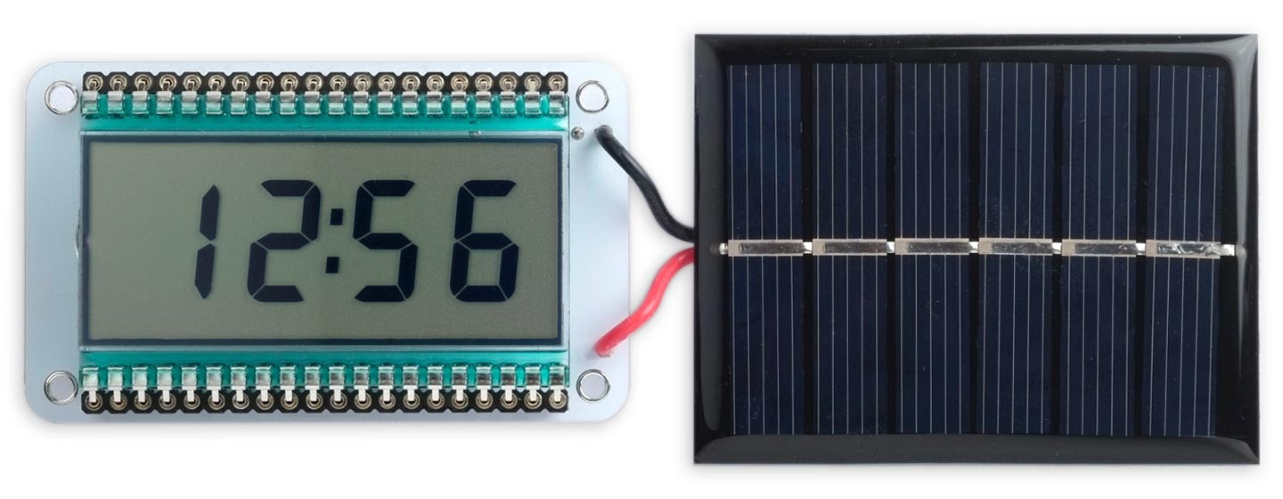
Low-power clock, based on an AVR128DA48, displays the time on an LCD display.
Every minute it also briefly displays the temperature, using the AVR128DA48's on-chip temperature sensor, and the battery voltage, by using the ADC to read its own supply voltage. There's also an I2C connection so you can add an external sensor, for example to show the humidity in addition to the other readings.
Introduction
Although liquid crystal displays (LCDs) are relatively old technology, they still offer several advantages over newer types of display, including low power, low cost, and readability.
I recently bought some Densitron LCD displays on eBay for a few pounds/dollars, and I'd been wanting to try building a low-power clock around them, to see just how low I could get the power consumption. The displays are a standard type, available with compatible pinouts from several manufacturers. They are called static (as opposed to multiplexed), which means that every segment comes to a separate pin on the edge connector. This makes 28 pins for the segments plus three decimal points, a colon, and a common pin, adding up to 33 pins altogether. The displays I've found usually have two common pins, and also typically have other special-purpose segments, such as a minus sign, in a 40-pin package.
The displays are usually clear, but when you apply a voltage of about 3.3V between a segment and the common line the segment turns black. The displays I'm using have a reflective backing; they are also available with a translucent backing so you can add a backlight behind them.
There's one catch; you can't use a DC voltage to turn on the segments, because this would cause electrolysis to occur which would slowly degrade the display. The solution is to use AC by switching the polarity across the segment at a low frequency; 32Hz is usually recommended. Fortunately this is easy to do in software [1].
LCD display options
Most 40-pin, 33mm row spacing displays should be compatible with this board; here are some I've found. These all have 4 digits and 3 decimal points on pins 5 to 27, 29 to 32, and 34 to 37, and commons on 1 and 40, plus a few extra symbols as shown:
| Display | Extra symbols | Link |
| Densitron DG-201208-RP | Colon (28), Triangle (38) | |
| Varitronix VI-402-DP-RC-S | Colon (28) | VI-402-DP-RC-S on Digikey.com |
| RS PRO 7-Segment LCD | Colon (28) | RS PRO 7-Segment LCD on RSOnline |
| Lumex LCD-S401C52TR | Colon (28) | LCD-S401C52TR on Mouser |
| EDC190 | Colon (28) | EDC190 on AliExpress |
| EDS805 | LB (2), Minus (3) | EDS805 on AliExpress |
The circuit
Here's the circuit of the Low-Power LCD Clock:
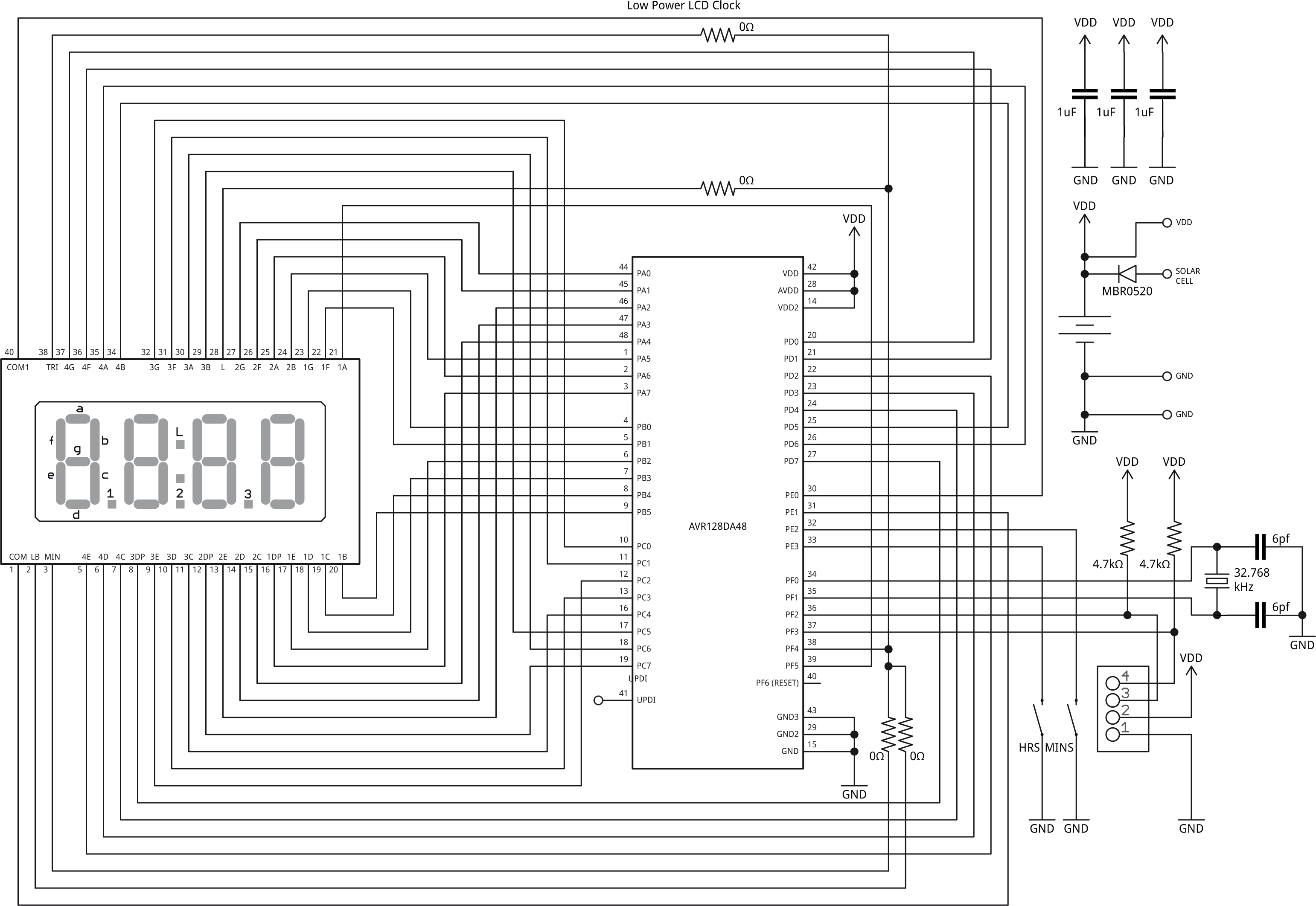
Circuit of the Low-Power LCD Clock based on an AVR128DA48.
The circuit is less complicated than it looks. Each segment simply connects to one I/O line on the processor. All the segments for one digit go to the same port, with the decimal point going to bit 7, segment A going to bit 6, through to segment G going to bit 0 (with a couple of exceptions explained below).
The display
The display is a four-digit seven-segment static LCD, with 40 pins and 33mm row spacing; see above for a list of suitable alternatives.
The crystal
The crystal I used is a 32.768kHz 3.2mm x 1.5mm SMD type with an accuracy of 20ppm and a load capacitance of 6pF [2]. To calculate the capacitor values I used the formula C = 2(CL - CS), where CL is the load capacitance 6pF, and CS is the stray capacitance which is usually estimated to be 2.5pF on a PCB. This gives C=7pF. I used the closest available value, 6pF.
Processor
The processor is an AVR128DA48 in a TQFP-48 package, but the PCB would work with a range of other 48-pin processors. The AVR128DB48 would be suitable, as would the lower memory versions of these two devices, down to the AVR32DA48 and AVR32DB48. However, you only save a few pence/cents by choosing the lower memory versions, so I don't really see the point.
The ATmega4809 and its lower-memory siblings, down to the ATmega809, are pin compatible with the DA and DB chips in the same packages, and so could also be used on this board; the only restriction is that the pins I've used for I2C, PF2 and PF3, only support slave I2C on the ATmega4809.
► Parts list
Construction
The PCB
Because of the number of interconnections I didn't fancy prototyping this project by hand, but went straight to designing a PCB in Eagle, and I sent it to PCBWay for manufacture. I tried to make the PCB as general purpose as possible. It caters for any of the displays in the above table; to select which of the extra symbols you want to display you need to fit an 0Ω resistor to the board to act as a link.
The display
The LCD display is mounted on the front of the board, with the components on the back. I mounted the LCD in low-profile header sockets [3] as I wanted to be able to try different displays, or you might be able to get it to make good enough contact without soldering. Alternatively you could solder it in the usual way.
Power supply
There's space for a 20mm coin cell holder, suitable for a CR2032 or similar:
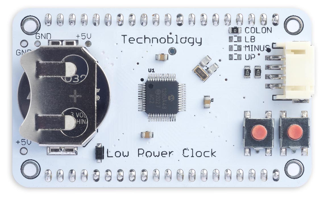
The low-power clock board, showing the CR2032 button cell holder.
Note that with some button cells the negative terminal is concave, and doesn't make good contact with the pad on the PCB; in this case melting some solder on the PCB contact should provide enough extra thickness.
Alternatively, if you want to power the clock from a 3V solar cell there are holes to allow you to fit a supercapacitor in place of the coin cell; I used a PowerStor 0.47F 5V one [4]:
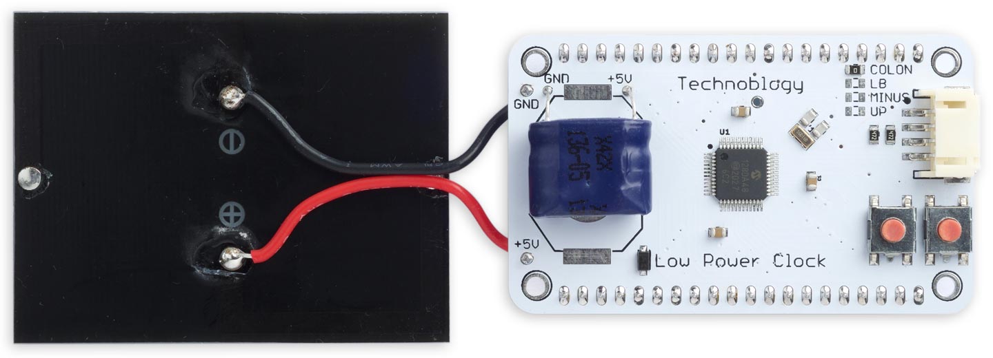
Using a solar cell to power the clock, with a supercapacitor in place of the button cell holder.
There are terminals to connect the photovoltaic cell at the edge of the board, with a Schottky diode in series with the solar cell to prevent it from draining the supercapacitor when there's no sun; I used a 3V 60x48mm solar cell from Pimoroni [5].
For details of the life you can expect from each option see Power consumption below.
I2C interface
The PCB also includes a 4-pin JST PH socket, providing an I2C interface compatible with Adafruit's STEMMA system or the Grove system. You can use this to connect a sensor to the board, for example to show the humidity as well as the time and temperature, or you could use it to make the board an I2C slave so it can be used as an I2C display for other projects.
The I2C interface is connected to PF2 (SDA1) and PF3 (SCL1). This I2C interface isn't supported by DxCore, but I plan to give some sample code for connecting an I2C sensor in a future article.
The program
Controlling the display
In the program I've numbered the digits 0 to 3 left to right. The port associated with each display digit is specified by the array Digit[]:
PORT_t *Digit[4] = { &PORTD, &PORTC, &PORTA, &PORTB };
There's no multiplexing, so to display a segment pattern we just need to write the appropriate value from the segment array, Char[0] to Char[11], to the port corresponding to the digit. Ports D, C, and A provide eight I/O lines each, so these map in a logical way to the seven segments and decimal point in digits 0 to 2. There's a slight complexity with digit 3 because Port B only has six I/O lines available, so the segment corresponding to bit 6 is provided by PF5. The colon or other symbol is controlled by PF4.
The I/O ports are set up by the routine PortSetup():
void PortSetup () {
  for (int p=0; p<4; p++) Digit[p]->DIR = 0xFF;       // All pins outputs
  PORTE.DIR = PIN0_bm | PIN1_bm;                      // COMs outputs, PE0 and PE1
  PORTF.DIR = PIN5_bm | PIN4_bm;                      // 1A, colon
}
Real-Time Clock
The clock uses the Real-Time Clock (RTC) peripheral controlled by a 32.768kHz crystal to keep accurate time. The code to set up the RTC is almost identical to my earlier projects Mega Tiny Time Watch [Updated] and Big Time. It is configured as a Periodic Interrupt Timer (PIT), generating a regular interrupt. In this project I've used a divisor of 512, which divides down the 32.768kHz crystal to give 64 interrupts a second.
The interrupt service routine first toggles all the I/O lines connected to the LCD segments, and the common connections. Every 32 calls, or every half second, it calculates the current time, and checks whether the buttons are pressed. If the MINS or HRS buttons are pressed it advances the time by a minute or an hour respectively. It then calls the routine DisplayTime() to update the time, or at the end of each minute it calls DisplayVoltage() to display the battery voltage for three seconds, followed by DisplayTemp() to display the temperature for three seconds:
ISR(RTC_PIT_vect) {
  static uint8_t cycles = 0;
  static unsigned long halfsecs;
  RTC.PITINTFLAGS = RTC_PI_bm;                        // Clear interrupt flag
  // Toggle segments
  for (int p=0; p<4; p++) Digit[p]->OUTTGL = 0xFF;    // Toggle all PORTA,B,C,D pins
  PORTE.OUTTGL = PIN0_bm | PIN1_bm;                   // Toggle COMs, PE0 and PE1
  PORTF.OUTTGL = PIN5_bm | PIN4_bm;                   // Toggle segment 1A, Colon

  cycles++;
  if (cycles < 32) return;
  cycles = 0;

  // Update time
  halfsecs = (halfsecs+1) % 172800;                   // 24 hours
  uint8_t ticks = halfsecs % 120;                     // Half-second ticks

  if (MinsButton()) halfsecs = ((halfsecs/7200)*60 + (halfsecs/120 + 1)%60)*120;
  if (HoursButton()) halfsecs = halfsecs + 7200;

  if (MinsButton() || HoursButton() || ticks < 108) DisplayTime(halfsecs);
  else if (ticks == 108) DisplayVoltage();
  else if (ticks == 114) DisplayTemp();
}
If you don't want to display the voltage, change the last three lines to:
  if (MinsButton() || HoursButton() || ticks < 114) DisplayTime(halfsecs);
  else if (ticks == 114) DisplayTemp();
Displaying the time
DisplayTime() copies the digits representing the current time to the corresponding output ports, specified by Digit[0] to Digit[3]. It also flashes the colon:
void DisplayTime (unsigned long halfsecs) {
  uint8_t minutes = (halfsecs / 120) % 60;
  #ifdef TWELVEHOUR
  uint8_t hours = (halfsecs / 7200) % 12 + 1;
  #else
  uint8_t hours = (halfsecs / 7200) % 24;
  #endif
  Digit[0]->OUT = Char[hours/10];
  Digit[1]->OUT = Char[hours%10];
  Digit[2]->OUT = Char[minutes/10];
  uint8_t units = Char[minutes%10];
  Digit[3]->OUT = units;
  uint8_t colon = (halfsecs & 1)<<4;                  // Toggle colon at 1Hz
  PORTF.OUT = (units>>1 & PIN5_bm) | colon;
}
Displaying the temperature
You can optionally also display the ambient temperature every minute:
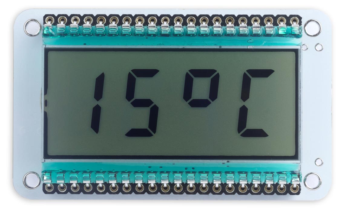
Optional temperature display on the low-power LCD clock.
DisplayTemp() calls the ADC to read the temperature sensor, converts the temperature to degrees Celsius, and displays it on the digits:
void DisplayTemp () {
  uint16_t offset = SIGROW.TEMPSENSE1;                // Read offset calibration
  uint16_t slope = SIGROW.TEMPSENSE0;                 // Read slope calibration
  ADC0.MUXPOS = ADC_MUXPOS_TEMPSENSE_gc;
  ADC0.CTRLA = ADC_ENABLE_bm;                         // Single, 12-bit, left adjust
  ADC0.COMMAND = ADC_STCONV_bm;                       // Start conversion
  while (ADC0.COMMAND & ADC_STCONV_bm);               // Wait for completion
  uint16_t adc_reading = ADC0.RES;                    // ADC conversion result
  uint32_t kelvin = ((uint32_t)(offset - adc_reading) * slope + 0x0800) >> 12;
  int celsius = abs(kelvin - 273);
  ADC0.CTRLA = 0;                                     // Disable ADC

  // Display it
  if (kelvin < 273) Digit[0]->OUT = Char[Minus];
    else Digit[0]->OUT = Char[celsius/10];
  Digit[1]->OUT = Char[celsius%10];
  Digit[2]->OUT = Char[Degree];
  uint8_t units = Char[Celsius];
  Digit[3]->OUT = units;
  PORTF.OUT = (units>>1 & PIN5_bm);                   // No colon
}
Unlike earlier AVR microcontrollers, where you had to calibrate the temperature sensor, the AVR DA and DB series have been calibrated during manufacture and contain calibration parameters in ROM. The temperature display is therefore pretty accurate without any additional calibration.
The temperature display routine will display subzero temperatures down to -9°C; hopefully your ambient temperature won't get lower than that.
Displaying the voltage
Another option is to display the battery voltage:
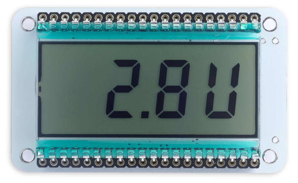
Optional voltage display on the low-power LCD clock.
A 'U' is the closest we can get to displaying a 'V' on the seven-segment displays.
DisplayVoltage() calls the ADC to read the battery voltage, converts the voltage to tenths of a volt, and displays it on the digits:
void DisplayVoltage () {
  ADC0.MUXPOS = ADC_MUXPOS_DACREF0_gc;                // Measure DACREF0
  ADC0.CTRLA = ADC_ENABLE_bm;                         // Single, 12-bit, left adjusted
  ADC0.COMMAND = ADC_STCONV_bm;                       // Start conversion
  while (ADC0.COMMAND & ADC_STCONV_bm);               // Wait for completion
  uint16_t adc_reading = ADC0.RES;                    // ADC conversion result
  uint16_t voltage = adc_reading/50;
  ADC0.CTRLA = 0;                                     // Disable ADC

  // Display it
  Digit[0]->OUT = Char[Space];
  Digit[1]->OUT = Char[voltage/10] | 0x80;            // Decimal point
  Digit[2]->OUT = Char[voltage%10];
  uint8_t units = Char[Vee];
  Digit[3]->OUT = units;
  PORTF.OUT = (units>>1 & PIN5_bm);                   // No colon
}
For a full explanation of how this works see my earlier article Measuring Your Own Supply Voltage.
Power consumption
I spent a bit of effort to get the power consumption as low as possible.
The processor spends most of its time in power-down sleep mode, to save power, and is woken up by the 64Hz interrupt from the Real-Time Clock peripheral. I measured the average power consumption at 3.3V for four different clock frequencies:
| Clock Frequency | 24MHz | 12MHz | 4MHz | 1MHz |
| Power Consumption | 9.5µA | 10.7µA | 11.3µA | 12.8µA |
Usually you'd expect the power consumption to increase with processor clock frequency, so at first sight these figures are puzzling. The explanation is that at higher clock frequencies the time taken to execute the interrupt service routine is shorter, allowing the processor to spend a higher proportion of the time asleep.
The 32.768kHz external crystal oscillator has a low-power mode, and selecting this reduced the average power consumption with a 24MHz clock from 9.5µA to 7.3µA. The AVR128DA48 datasheet doesn't seem to mention any downside to choosing the low-power mode, so I used this setting.
A CR2032 coin cell has a typical capacity of 225 mAh, so with a consumption of 7.3µA the expected battery life of the clock is 225/0.0073/24/365 or about 3.5 years.
With a 0.47F supercapacitor you can expect a current of 0.47A for 1 second. This gives an expected life of 0.47/7.3x10‑6/60/60 or about 18 hours, which I confirmed by testing it. This should be sufficient to keep the clock running overnight with a suitable solar cell providing power during daylight.
Setting the time
The MINS and HRS buttons allow you to set the clock to the correct time. Holding a button down steps through the minutes or hours twice a second.
The buttons use I/O pins PE2 and PE3, and they are set up by ButtonSetup():
void ButtonSetup () {
  PORTE.PIN3CTRL = PORT_PULLUPEN_bm;                  // PE3 input pullup
  PORTE.PIN2CTRL = PORT_PULLUPEN_bm;                  // PE2 input pullup
}
The buttons are read by MinsButton() and HoursButton() which return true if the button is being pressed:
boolean MinsButton () {
  return (PORTE.IN & PIN2_bm) == 0;                   // True if button pressed
}

boolean HoursButton () {
  return (PORTE.IN & PIN3_bm) == 0;                   // True if button pressed
}
Pressing the MINS button resets the seconds to zero; this is designed so you can set the clock to the precise second, such as from a radio timecode. To do this, set the minutes to the current minute, and at the timecode at the end of the minute step the minutes on by one.
Also, incrementing the minutes past 59 doesn't increment the hours. This would be annoying if you're setting the minutes after you've already set the hours to the correct time.
These two features are implemented by the statement:
if (MinsButton()) halfsecs = ((halfsecs/7200)*60 + (halfsecs/120 + 1)%60)*120;
The HRS button doesn't affect the seconds and minutes timing; this is designed to allow you to switch between Standard Time and Daylight Saving Time without affecting the clock setting.
This is implemented by the statement:
if (HoursButton()) halfsecs = halfsecs + 7200;
Compiling the program
Compile the programs using Spence Konde's Dx Core on GitHub. Choose the AVR DA-series (no bootloader) option under the DxCore heading on the Board menu. Check that the subsequent options are set as follows (ignore any other options):
Chip: "AVR128DA48"
Clock Speed: "24 MHz internal"
Programmer: "jtag2updi (megaTinyCore)"
Then upload the program to the AVR128DA48 using a UPDI programmer. The DxCore now supports the following two options:
- Make a UPDI programmer from an Arduino Uno, or other ATmega328P-based board, as described in Make UPDI Programmer, and set the Programmer option to "jtag2updi".
- Use a USB to Serial board, such as the SparkFun FTDI Basic board [6], connect TX to the UPDI pin via a 4.7kΩ resistor, connect RX directly to the UPDI pin, and set the Programmer option to "Serial port and 4.7k (pyupdi style)".
You can ignore the error "Cannot locate flash and boot memories in description".
Resources
Here's the whole Low-Power LCD Clock program: Low-Power LCD Clock Program.
Get the Eagle files for the PCBs from GitHub so you can make yourself a board, at: https://github.com/technoblogy/lcd-clock.
Or order a board from OSH Park here: Low-Power LCD Clock.
Or order a board from PCBWay here: Low-Power LCD Clock.
- ^ AVR241: Direct driving of LCD display using general IO on Microchip.com.
- ^ ABS07-120-32.768kHz-T on Farnell.
- ^ Winslow 20 Way 1 Row Straight Socket Strip on RS-Online.
- ^ PowerStor PB-5R0V474-R on Mouser.co.uk.
- ^ 3.0V 100mA Polycrystalline Solar Cell on Pimoroni.
- ^ SparkFun FTDI Basic Breakout - 5V on Sparkfun.
blog comments powered by Disqus