Secret Maze PCB
14th March 2018
Since publishing my Secret Maze project I've designed a printed circuit board for the circuit, to make it easier to build a convenient pocket version of the game:
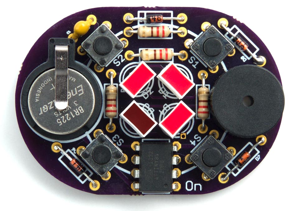
The printed circuit board designed for my ATtiny85-based Secret Maze game.
To avoid the need for an on/off switch I've updated the program to automatically go to sleep if there has been no keypress for 30 seconds; this has the advantage that it's not possible to inadvertently leave the game on, and run down the battery. To wake up the game you press the button labelled On on the PCB. The power consumption in sleep mode is about 0.25µA at 3V, which is negligible.
For a newer version of this project see Secret Maze 2.
Construction
I designed the board in Eagle and sent it to OSH Park for fabrication [1]. Here's the layout of both sides of the PCB:
There's a link to the Eagle files at the end of the article if you want to make yourself a board.
The printed circuit board is designed for through-hole components, so it should be suitable for people without much soldering experience. I made it as compact as possible, with the pushbuttons arranged in a diamond shape; this doesn't affect the maze as long as you make sure you hold the board in a consistent orientation.
I recommend using the ATtiny85V variant of the processor as this is rated down to 1.8V, so it will extend the life as the battery fades. The circuit is powered by a 12mm 3V coin cell; types CR1216, CR1220, or CR1225 are suitable. The battery fits in a through-hole 12mm coin cell holder [2].
The board is designed for standard 5mm LEDs, but will also accommodate single-bar LEDs [3] which give a nice visual representation of the four walls of the maze. I recommend using red LEDs, as these are the brightest when powered fom a 3V battery. The buzzer is a 12mm (0.5") diameter piezo buzzer.
I programmed the ATtiny85 after I had soldered it onto the circuit board by piggy-backing an 8-pin IC socket on top of it, and then plugged in the wires from my Tiny AVR Programmer board. Alternatively you could program the ATtiny85 in the socket on the Tiny AVR Programmer board before soldering it in, or use an IC socket.
The program
The program is essentially the same as in the original Secret Maze article, with the addition of a sleep timer to avoid the need for an on/off switch. A counter puts the processor to sleep after 30 secs of inactivity. Here's the loop that waits for a keypress:
  do {                                   // Go to sleep after Timeout
    if (Mymillis() - Start > Timeout*1000) {
      TIMSK = 0;                         // Disable interrupt
      DDRB = 0b1000;
      PORTB = 0b0100;                    // Set up Down pushbutton
      GIMSK = 1<<INT0;                   // Enable interrupt on INT0 (PB2)
      sleep_enable();
      sleep_cpu();
      GIMSK = 0;                         // Turn off INT0 interrupt
      TIMSK = 1<<OCIE0A;                 // Enable Timer/Counter0 interrupt
      Buttons = 0b100;                   // We pressed button on PB2
      while (Buttons != 0);              // Ignore this keypress
      Start = Mymillis();
    }
  } while (Buttons == 0);                // Wait for keypress
Because the program uses both of the ATtiny85's timer/counters the Arduino millis() function is not available, so I've provided my own millisecond timer, Mymillis(), to time the timeout. If the elapsed time exceeds Timeout the program goes into sleep mode.
Before putting the processor to sleep it first disables the multiplexing interrupt. It then sets up one of the buttons, marked On on the PCB, so this can be used to wake up the processor from sleep using the INT0 interrupt. The button is connected between PB2 and PB3, so PB3 is set up as a low output, and PB2/INT0 as an input with a pullup. Finally the INT0 interrupt is enabled, and the processor is put to sleep.
Pressing the On button generates an INT0 interrupt which wakes up the processor. The program waits for the key to be released, so it won't affect the maze, and then execution resumes.
Here's the whole updated Secret Maze program: Secret Maze PCB Program.
Alternatively, get it on GitHub here together with the Eagle files for the PCB: Secret Maze on GitHub.
Or order a board from OSH Park here: Secret Maze Board.
Updates
16th March 2018: Added a note about using the ATtiny85V.
24th March 2018: Updated the program to return you to the start of the maze after a short delay when you've successfully reached the goal.
- ^ OSH Park PC prototyping service.
- ^ Keystone CR1216, CR1220, CR1225 PCB Battery Holder on RS-Online.
- ^ L-1043RDT LED Bar Graph Array, Red, 1 LED on Farnell.com.
blog comments powered by Disqus