Digital Music Box [Updated]
23rd February 2016
This project is a simple digital music box, which can play tunes in an analogous way to a traditional mechanical music box [1]. It's based on an ATtiny85, and uses no other components apart from a loudspeaker and capacitor:
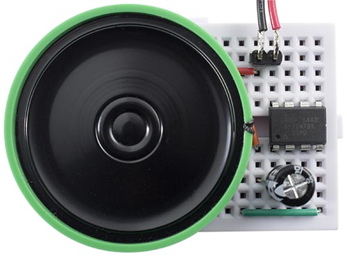
Digital music box, based on an ATtiny85.
The notes have a bell-like sound, with a decaying envelope, and there are four channels, so up to four notes can play simultaneously. The waveforms and envelopes are calculated dynamically, avoiding the need for lookup tables of precalculated values. My demonstration program plays "Happy Birthday"; here's what it sounds like: musicbox.mp3.
You can easily program it to play any tune you like, and it could be used as the basis for an electronic greeting card, electronic doorbell, or other music-based project.
Programming the tune
The tune is specified by setting bits in a series of 32-bit (long) numbers, a bit like the pegs on a mechanical musical box. This gives the music box a range of just over two octaves. The chords are played with a constant tempo of 4 beats per second, so to insert a rest you provide a row of zeros. For example, here are the codings for the first verse of "Happy Birthday":
The first verse of "Happy Birthday" coded as 12 32-bit binary numbers.
The tune is stored in program memory, and the program takes less than 1Kbytes; each chord takes 4 bytes, so there's room for a tune of about 1800 chords!
The chords are output using a Watchdog interrupt. Each call to the interrupt service routine reads the next chord definition, and then scans through the 32 bits, outputting a note when it finds a '1':
ISR(WDT_vect) {
  sei();   // Allow interrupts
  WDTCR |= 1<<WDIE;
  unsigned long Chord = pgm_read_dword(&Tune[TunePtr]);
  if (Chord == 0xFF) return;
  TunePtr++;
  // Read the bits in Chord
  for (int Note = 0; Note < 32; Note++) {
    if ((Chord & 0x80000000) != 0) {
      Freq[Chan] = Scale[Note];
      Amp[Chan] = 1<<(Decay+5);
      Chan = (Chan + 1) % Channels;
    }
    Chord = Chord<<1;
  }
}
The end of the tune is marked by a value of 0xFF.
Generating the waveforms
Like my earlier project Tiny Synth this music box uses DDS (Direct Digital Synthesis) to generate the waveforms. However, the Tiny Synth didn't include envelopes; the sounds were either on or off, like an organ. To make this project sound like a music box I wanted to give the waveforms decaying envelopes, like bells. This is usually achieved by using a table of values to define the shape of the envelope, and then multiplying the current value of the waveform by successive values of the envelope. However, the ATtiny85 doesn't have a hardware multiply instruction, and a software multiply would be too slow for this, as it needs to be performed for each sample at the 20kHz sample rate. Also, I wanted to avoid having a table of envelope values.
The solution is to make the basic waveform a square wave, so we only need to multiply the amplitude of the envelope by 1 or -1. Also, by making the shape of the envelope a linear decay, so we can calculate the amplitude values simply by decrementing a counter.
Setup
The music box uses both of the ATtiny85 timers, and the watchdog timer. These are configured in setup():
void setup() {
  // Enable 64 MHz PLL and use as source for Timer1
  PLLCSR = 1<<PCKE | 1<<PLLE;

  // Set up Timer/Counter1 for PWM output
  TIMSK = 0;                     // Timer interrupts OFF
  TCCR1 = 1<<CS10;               // 1:1 prescale
  GTCCR = 1<<PWM1B | 2<<COM1B0;  // PWM B, clear on match

  OCR1B = 128;
  DDRB = 1<<DDB4;                // Enable PWM output on pin 4

  // Set up Timer/Counter0 for 20kHz interrupt to output samples.
  TCCR0A = 3<<WGM00;             // Fast PWM
  TCCR0B = 1<<WGM02 | 2<<CS00;   // 1/8 prescale
  OCR0A = 99;                    // Divide by 100
  TIMSK = 1<<OCIE0A;             // Enable compare match, disable overflow

  // Set up Watchdog timer for 4 Hz interrupt for note output.
  WDTCR = 1<<WDIE | Tempo<<WDP0; // 4 Hz interrupt
}
The first section turns on the 64MHz Phase-Locked Loop (PLL), and specifies this as the clock source for Timer/Counter1.
Timer/Counter1 is then set up in PWM mode, to make it act as an analogue-to-digital converter, using the value in OCR1B to vary the duty cycle. The frequency of the square wave is specified by OCR1C; we leave it at its default value, 255, which divides the clock by 256, giving a 250kHz square wave. This is high enough above our sampling rate to avoid anti-aliasing problems.
Timer/Counter0 is used to generate an interrupt to output the samples. The rate of this interrupt is the 16MHz system clock divided by a prescaler of 8, and a value in OCR0A of 99+1, giving 20kHz. The interrupt calls an Interrupt Service Routine ISR(TIMER0_COMPA_vect) which calculates and outputs the samples.
Finally the Watchdog timer is configured to give a 4Hz interrupt, which is used to play each chord in the tune.
Outputting the samples
For each channel there are three variables; Freq[], the current note value, Acc[], the phase accumulator, and Amp[], the envelope amplitude value. For each sample the Freq[] value is added to the phase accumulator, Acc[]. The top bit of Acc[] is used to generate the square wave for the channel. The larger the value of Freq[], the higher the frequency generated by the top bit. Finally, the waveform is multiplied by the envelope, Amp[]. The four channels are added together, and the result is output to the analogue output.
The critical part of the program is the Timer/Counter0 interrupt service routine, which outputs the waveform samples to the analogue output, and this gets called at a rate of 20kHz. For each channel it updates the frequency accumulator and amplitude, and calculates the value of the current note. These are then summed together, and the sum is output to the Timer/Counter1 compare register OCR1B to give an analogue value on pin 4:
ISR(TIMER0_COMPA_vect) {
  signed char Temp, Mask, Env, Note, Sum=0;
  for (int c = 0; c < Channels; c++) {
    Acc[c] = Acc[c] + Freq[c];
    Amp[c] = Amp[c] - (Amp[c] != 0);
    Temp = Acc[c] >> 8;
    Mask = Temp >> 7;
    Env = Amp[c] >> Decay;
    Note = (Env ^ Mask) + (Mask & 1);
    Sum = Sum + Note;
  }
  OCR1B = Sum + 128;
}
To minimise clicks it's important that the code in this routine takes a consistent execution time, so conditional statements should be avoided.
The envelope of each note is generated by an amplitude counter for each channel, Amp[c], which is decremented until it reaches zero. The obvious way of doing this is:
if (Amp[c] != 0) Amp[c]--;
I replaced this with the following equivalent statement, which avoids the conditional branch:
Amp[c] = Amp[c] - (Amp[c] != 0);
The square wave is generated by testing the top bit of the accumulator for each channel, Acc[c], and Mask is set to 0x00 if the bit is zero or 0xFF if it is set, which could be done like this:
if ((Acc[c] & 0x8000) != 0) Mask = 0xFF; else Mask = 0x00;
This is the alternative, avoiding a branch:
Temp = Acc[c] >> 8;
Mask = Temp >> 7;
where Temp and Mask are declared as signed char (8-bit) numbers.
Finally, the note is set either + or - the current amplitude of the envelope, Env:
if (Mask != 0) Note = Env; else Note = - Env;
This is coded without a conditional as follows:
Note = (Env ^ Mask) + (Mask & 1);
The circuit
The circuit is the same as for my earlier article, Tiny Synth, with the PWM output fed straight to an 8Ω loudspeaker via an electrolytic capacitor to remove the DC. The inductance of the loudspeaker filters out the high-frequency components of the waveform:
Circuit for the music box, based on an ATtiny85.
I powered the circuit from three 1.5V alkaline AAA batteries, which gave just enough voltage. If you're using an external power supply and you get distorted sound or no sound you may need to decouple the supply with 100nF and 47µF capacitors across the supply lines near the ATtiny85.
For a greeting card you might want to use a thin speaker, available from Sparkfun [2] or HobbyTronics in the UK [3].
If you want to feed the output to an audio amplifier you must include a low-pass filter, otherwise you risk overloading the amplifier. See Waveform Generation using an ATtiny85 for a suitable circuit.
Compiling the program
To be capable of supporting four channels the ATtiny85 needs to be run with a 16MHz clock; fortunately it provides a 16MHz clock option, without the need for a crystal, using the internal PLL to boost the internal 8MHz clock to 16MHz.
I compiled the program using Spence Konde's ATTiny Core [4]. Choose the ATtiny25/45/85 option under the ATtinyCore heading on the Board menu. Then choose Timer 1 Clock: CPU, B.O.D. Disabled, ATtiny85, 16 MHz (PLL) from the subsequent menus. Choose Burn Bootloader to set the fuses appropriately. Then upload the program using ISP (in-system programming); I used Sparkfun's Tiny AVR Programmer Board; see ATtiny-Based Beginner's Kit.
The program doesn't use any Arduino-specific functions, so it should be possible to compile it with any ATtiny85 core, or an empty core; see Using the Arduino IDE Without Cores.
Here's the whole Music Box program, including the data for "Happy Birthday" I used in the prototype: Music Box Program.
Update
16th March 2016: I've fixed a bug in the program which caused distorted output when the program was compiled with version 1.5.x or later of the Arduino IDE. It turns out that the bug was due to failing to initialize the variable Sum in the ISR(TIMER0_COMPA_vect) routine, and I've corrected it in the above program. I'm not sure why the bug didn't cause a problem with version 1.0.6 of the Arduino IDE.
6th November 2017: I've updated the description to use Spence Konde's ATTinyCore.
- ^ For example, this Happy Birthday Crank Music Box on Kikkerland.
- ^ Thin Speaker on Sparkfun.
- ^ Thin Speaker on HobbyTronics.
- ^ ATTinyCore on GitHub.
blog comments powered by Disqus