IR Remote Control Receiver
3rd April 2015
This article describes a simple interrupt-driven routine for the ATtiny85 to decode codes from an infrared remote control. It supports the NEC protocol, used by many remote controls from the Far East, such as the Adafruit remote control [1] (available from Proto-PIC in the UK [2]).
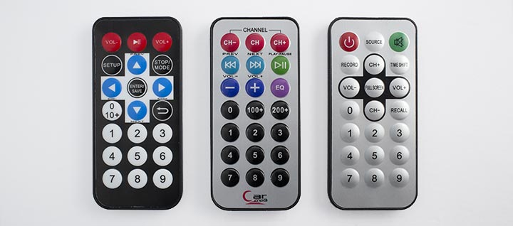
A selection of suitable NEC-format IR remote controls, from Adafruit, MakerStudio, and eBay (left to right).
I tested it with a simple demonstration circuit. This toggles one of three LEDs on and off when one of the keys 1 to 3 is pressed on the remote, and allows you to adjust the brightness of the fourth LED with the VOL+ and VOL- keys:
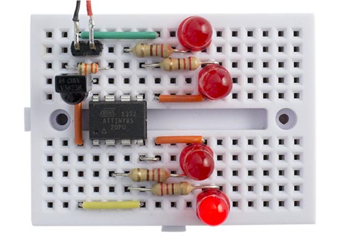
Test circuit for the interrupt-driven NEC remote control receiver program.
Approach
I know there are existing IR remote control libraries, but they seem over-complicated, and they rely on polling the remote control input. I decided to try writing a simple IR remote control receiver using interrupts instead.
The advantage of using an interrupt routine is that the program can respond to the remote control while carrying out another intensive task, such as navigating a robot or operating a sequence of LEDs. Another advantage is that an IR remote control key can be used to wake the processor from sleep.
This routine also handles the repeat code which is transmitted if you keep a key held down on the remote. This is useful if, for example, you want to use the VOL- and VOL+ keys to change the brightness of an LED. The demo program illustrates this application with the test circuit.
Remote control code
The code emitted by NEC-format remote controls consists of a long start pulse, called the AGC pulse. This is followed 13.5ms later by start of the first data bit. There are a total of 32 data bits, 16 of which are the address to identify the product, and 16 are the command, to identify which key was pressed. For example, here's the code for the '5' key on the Adafruit remote control:
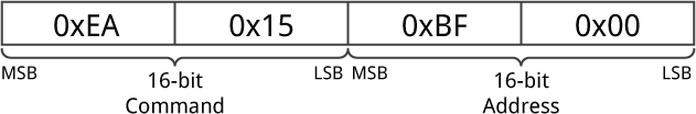
On this remote control every keypress has the same two-byte address: 0xBF00. The lower byte of the command field identifies the key, and the upper byte of the command field is just the inverse of the lower byte.
If a key is kept held down its code is followed by a sequence of AGC pulses 11.25ms long at regular 110ms intervals until the key is released.
Note that in the NEC protocol the bits are transmitted in reverse order, LSB first, so the first two bytes transmitted are the address, followed by the command, and finally the command inverted. For full details of the NEC protocol see my earlier article IR Remote Control Tool (NEC).
How it works
The IR remote control receiver routine uses Timer/Counter0 as a simple counter to measure the intervals between interrupts. The counter uses a prescaler of 64, so with the 1MHz clock each count corresponds to 64µs. If you're using a different clock frequency from 1MHz you'll need to change the program accordingly.
The output of the IR detector is normally high, and goes low when it detects a 36kHz carrier pulse. We therefore want to trigger the interrupt service routine on the falling edge of each pulse from the detector. The IR detector is connected to PB2 which allows us to use the flexible interrupt INT0, with the option of triggering on falling edges only. If you want to use a different input pin you'll need to use a pin change interrupt instead, and check for a falling edge in software.
Timer/Counter0 and INT0 are set up in the setup() routine:
void setup() {
  // Set up LEDs
  for (int x=0; x<4; x++) pinMode(LED[x], OUTPUT);
  // Set up Timer/Counter0 (assumes 1MHz clock)
  TCCR0A = 0;                 // No compare matches
  TCCR0B = 3<<CS00;           // Prescaler /64
  // Set up INT0 interrupt on PB2
  MCUCR = MCUCR | 2<<ISC00;   // Interrupt on falling edge
  GIMSK = GIMSK | 1<<INT0;    // Enable INT0
  NextBit = 32;               // Wait for AGC start pulse
}
The routine leaves Timer/Counter1 free for use by the ATtiny core, for delay(), millis(), micros(), and analogWrite() on PB4.
Interrupt service routine
The interrupt service routine is very simple; it starts in a waiting state, checking for the initial AGC pulse and gap. Once this has been found it processes each of the 32 data bits. The variable NextBit is used to keep track of where we are in this sequence. It takes a value of 32 when waiting for the AGC start pulse, and 0 to 31 during each of the data bits. The received code is stored in a 32-bit unsigned long variable RecdData.
The routine checks that the length of the AGC pulse and gap is within 10% of the required 13.5ms, corresponding to a count of 211, and if so sets NextBit to 0 to start reading the code. It also checks whether the AGC pulse and gap is within 10% of the 11.25ms width of a repeat code, corresponding to a count of 176, and if so calls ReceivedCode(1). If the length of the AGC pulse and gap lies outside these ranges the routine stays in the waiting state.
For each bit the routine checks its length. A 0-bit has a length of 1.125ms corresponding to a count of 18, and a 1-bit has a length of 2.25ms corresponding to a count of 35. If it's a 1-bit the appropriate bit is set in RecdData. If a bit is too long, or the overflow flag is set indicating that the counter has wrapped around, the processing of the code is abandoned and the routine returns to the waiting state.
When the interrupt routine has received the last bit it calls ReceivedCode(0) to act on the code. If necessary, this could put the code into a buffer and set a flag to indicate that a code is available. In this sample application ReceivedCode() simply changes one of the ATtiny85 outputs, PB0, PB1, PB3, or PB4 depending on which key was pressed on the remote.
ISR(INT0_vect) {
  int Time = TCNT0;
  int Overflow = TIFR & 1<<TOV0;
  // Keep looking for AGC pulse and gap
  if (NextBit == 32) {
    if ((Time >= 194) && (Time <= 228) && (Overflow == 0)) {
      RecdData = 0; NextBit = 0;
    } else if ((Time >= 159) && (Time <= 193) && (Overflow == 0)) ReceivedCode(1);
  // Data bit
  } else {
    if ((Time > 44) || (Overflow != 0)) NextBit = 32; // Invalid - restart
    else {
      if (Time > 26) RecdData = RecdData | ((unsigned long) 1<<NextBit);
      if (NextBit == 31) ReceivedCode(0);
      NextBit++;
    }
  }
  TCNT0 = 0;                  // Clear counter
  TIFR = TIFR | 1<<TOV0;      // Clear overflow
  GIFR = GIFR | 1<<INTF0;     // Clear INT0 flag
}
Demonstration program
The demonstration program first checks that the correct address code has been received to identify the remote control. For keys 1 to 3, corresponding to codes 0x10 to 0x12, it toggles the corresponding LED. For the VOL+ and VOL- keys, corresponding to key codes 0x02 and 0x00, it uses analogWrite() to adjust the brightness of LED 4:
void ReceivedCode(boolean Repeat) {
  // Check for correct remote control
  if ((RecdData & 0xFFFF) != 0xbf00) return;
  // Read key pressed
  int key = RecdData>>16 & 0xFF;
  // Keys 1, 2, and 3 toggle the corresponding LED
  if ((key >= 0x10) && (key <= 0x12) && !Repeat) {
    int pin = LED[key - 0x10];
    digitalWrite(pin, !digitalRead(pin));
  // Keys VOL- and VOL+ adjust the brightness of LED 4
  } else if (key == 0x02) analogWrite(4, Brightness++);
  else if (key == 0x00) analogWrite(4, Brightness--);
}
Finding the IR codes for a remote
If you want to work out the IR codes generated by an unknown infrared remote control you could build my previous project, IR Remote Control Tool (NEC). Alternatively you can use this project by connecting a piezo speaker between I/O pin 0 and ground, and replacing the ReceivedCode() routine by the following debugging routine:
void ReceivedCode(boolean Repeat) {
  for (unsigned long b=0x80000000; b!=0; b = b>>1) {
    for (unsigned int i=0; i<2500; i++) {
      if (RecdData & b) digitalWrite(0, (i & 8)); else digitalWrite(0, (i & 16));
    }
    for (unsigned int i=0; i<2500; i++) digitalWrite(0, (i & 0));
  }
}
This slowly beeps out the 32-bit code as a series of audible high and low beeps, MSB first, with a high beep representing a '1' and a low beep representing a '0'. It therefore provides a rough and ready way of revealing the code produced by each key.
Circuit
Here's the circuit I used to test the IR remote control receiver. It uses a 38kHz infrared receiver module available from Sparkfun [3], or from HobbyTronics in the UK [4]:
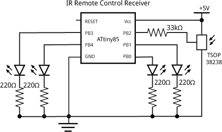
Test circuit for the interrupt-driven NEC remote control receiver program.
The 33kΩ resistor isn't strictly necessary, but it avoids errors when uploading programs to the ATtiny85 by isolating the output from the IR receiver from PB2 on the ATtiny85. Alternatively, remove the IR receiver from the breadboard while uploading.
Compiling the program
I compiled the program using the ATtiny core extension to the Arduino IDE [5]. Select the ATtiny85 @ 1 MHz (internal oscillator; BOD disabled) option on the Boards menu and choose Burn Bootloader to set the fuses appropriately using the Tiny AVR Programmer Board; see ATtiny-Based Beginner's Kit. Then upload the program to the ATtiny85.
Here's the whole ATtiny85 IR Remote Control Receiver program: IR Remote Control Receiver Program.
- ^ Mini Remote Control on Adafruit.
- ^ Mini Remote Control on Proto-PIC.
- ^ IR Receiver Diode - TSOP38238 on SparkFun.
- ^ Infra Red Receiver Module on HobbyTronics.
- ^ ATtiny core for Arduino: arduino-tiny on Google Code.
blog comments powered by Disqus