Tiny Lisp Computer 2 PCB
6th February 2017
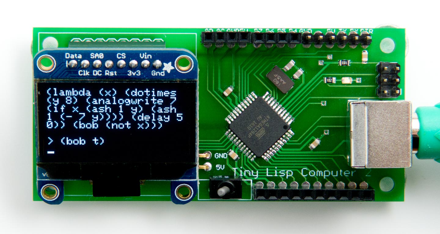
Last October I described my Tiny Lisp Computer 2, a small self-contained computer based on an ATmega1284, with its own display and keyboard interface, that you can use to program in Lisp. I've now designed a printed circuit board for the computer, based on SMD components:

The Tiny Lisp Computer PCB, based on an ATmega1284, that you can program in Lisp.
The PCB Eagle files are available from Github; see the link at the end of the article.
The computer is programmed in uLisp, my compact Lisp interpreter for the Arduino. This allows you to control the I/O ports directly, access I2C and SPI peripherals, and write small programs to automate functions. You can also save programs to EEPROM so they are retained when the power is disconnected, and they can be configured to run automatically on restart.
The board includes a connector for a PS/2 keyboard. I tested it with the Adafruit PS/2 keyboard [1], a compact low-cost keyboard that also supports USB. Alternatively there are low-cost PS/2 keyboards available on eBay.
I designed the PCB in Eagle and ordered a batch of boards from Seeed Fusion [2].
Example program
The computer has an LED connected to PB7, which is Arduino pin 7, and this is one of the analogue outputs. The following program uses analogwrite to pulsate the LED smoothly on and off:
(defun bob (x)
  (dotimes (y 8)
    (analogwrite
     7
     (if x (ash 1 y)
       (ash 1 (- 7 y))))
    (delay 50))
  (bob (not x)))
It outputs the values 1, 2, 4, 8, 16, 32, 64, and 128 to the analogue output, then the same values in the reverse order, and so on until you stop the program by pressing the Esc key.
Connectors
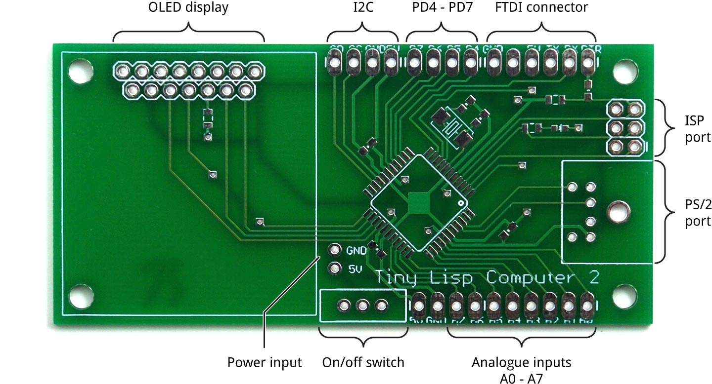
The PCB provides the following connectors, catering for most programming and interfacing requirements:

The external connections on the Tiny Lisp Computer PCB.
Components
The PCB uses 0805 resistors, capacitors, and an LED. I used a Youyue 858D+ hot air gun at 250°C to solder the SMD components onto the front of the board, but with care it should be possible to assemble it by hand using a fine-tipped soldering iron.
The PCB is designed for a two-pad SMD crystal. I used an Abracon ABM7 16.000MHz type.
The board accommodates the Adafruit 1.3" 128x64 SPI/I2C OLED display, which is based on the SSD1306 driver chip [3], or Pimoroni [4]. I plugged the display into an 8-way header socket, so it sits up at an angle from the PCB.
The board also accommodates the 1.3" 128x64 SPI 7-pin OLED displays available from Banggood [5] or AliExpress. These are based on a slightly different driver chip, the SH1106. A constant SH1106 in the program should be set to 0 for SSD1306 displays (the default), and 1 for SH1106 displays.
Installing a bootloader
To use the ATmega1284P with the Arduino core functions I used Jack Christensen's Mighty 1284P core, which works happily with version 1.6.x of the Arduino IDE [6].
Assuming you have bought an unprogrammed ATmega1284P you will first need to install a bootloader. I use an Arduino Uno as an ISP programmer:
- Install the Mighty 1284P core.
- On the Tools -> Board submenu choose "maniacbug" Mighty 1284p 16MHz using Optiboot.
- Select the sketch File -> Examples -> 11.ArduinoISP -> ArduinoISP and upload it to the Arduino Uno.
- Select Tools -> Programmer -> Arduino as ISP.
- Select Tools -> Burn Bootloader.
You should then be able to disconnect the Arduino Uno.
Uploading the Tiny Lisp Computer
The next step is to install the Tiny Lisp Computer code, using an FTDI USB-to-serial converter plugged into the FTDI connector on the PCB. There are several alternatives available; I used the FTDI Basic Breakout from Sparkfun [7], available from HobbyTronics in the UK [8].
- On the Tools -> Board submenu choose "maniacbug" Mighty 1284p 16MHz using Optiboot.
- Select the USB port from the Tools -> Port submenu.
- Click the Upload button.
Get the latest Tiny Lisp Computer source from GitHub, together with the Eagle files for the PCB so you can make yourself a board, at: https://github.com/technoblogy/tiny-lisp-computer.
- ^ Miniature Keyboard - Microcontroller Friendly PS/2 and USB on Adafruit.
- ^ Seeed Fusion PCB service.
- ^ Monochrome 1.3" 128x64 OLED Graphic Display on Adafruit.
- ^ Monochrome 1.3" 128x64 OLED Graphic Display on Pimoroni.
- ^ 1.3 Inch 7 Pin White OLED 128x64 SPI Interface Display Module on Banggood.
- ^ Mighty 1284P core on Github.
- ^ FTDI Basic Breakout on Sparkfun.
- ^ FTDI Basic Breakout on HobbyTronics.
blog comments powered by Disqus
