Sony NEX/Alpha Remote Control
12th April 2015
This article describes an infrared remote control I built to operate the shutter of my Sony NEX-5 camera remotely, for taking wildlife photographs. The remote control is based on an ATtiny85, and was built on a small prototyping board:
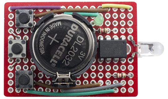
Three-button remote control circuit, for triggering the shutter of a Sony NEX or Alpha camera.
It provides three buttons with the following functions (from top to bottom): trigger the shutter immediately, trigger the shutter with a 2-second delay to allow the autofocus to work, and turn on/off video capture.
It could be connected to a PIR motion detector to trigger the camera when motion is detected, or to a laser or infrared light beam, to trigger the camera when a beam is broken. It could also be used to trigger the camera at regular intervals, for time-lapse photography.
Operation
I tested the remote control with my Sony NEX-5:
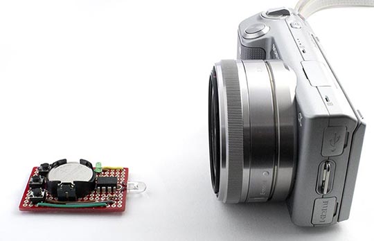
Testing the Sony NEX/Alpha remote control with a Sony NEX-5.
To control the camera using the remote control you have to set the Drive Mode to the Remote Cdr. option in the Camera menu. The camera still operates normally in this mode, but the auto sleep function is disabled to ensure that the camera won't go to sleep while waiting for your remote-control command.
Sony SIRC code
By analysing the codes from a cheap two-button remote I bought on eBay I discovered that the Sony NEX/Alpha cameras use the Sony SIRC protocol, which is similar to the NEC code, but with different timings. It uses a 20 bit code consisting of a 13 bits address and a 7-bit command code. For a full description of this protocol see San Bergmans's excellent SB-Projects site [1].
The data is encoded using pulse width encoding. A zero consists of a 600µs pulse of tone, and a one consists of a 1.2ms pulse of tone. In each case they are followed by a 600µs gap:
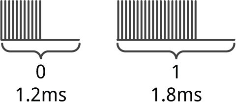
The zero pulse consists of 24 cycles at 40kHz:

A one pulse is twice as long as this. The pulses usually have a mark/space ratio of 1:4, to reduce the current consumption.
Each code sequence starts with a 2.4ms start pulse, followed by a 600µs gap, and then the data:
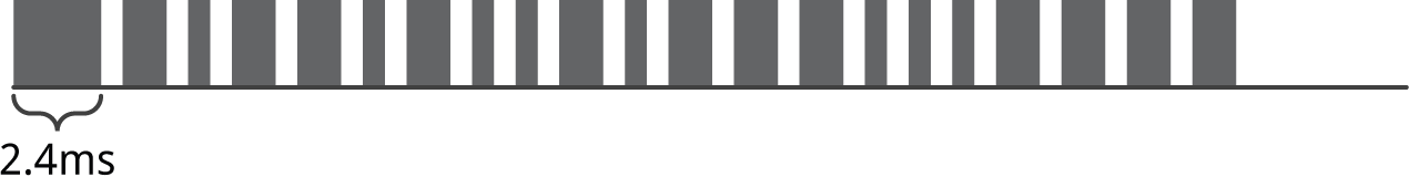
The data consists of 20 bits, a 7-bit command followed by a 13-bit address, shown in the order in which they are transmitted (left to right):
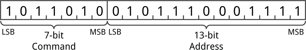
The above examples show the command 0x2D and the address 0x1E3A used for the Shutter command on the Sony NEX/Alpha cameras.
Command codes
The following table gives the codes for the Sony NEX/Alpha shutter operation commands:
| Command | Code | Decription |
| Shutter | 0x2D | Operates the shutter immediately. |
| 2-Sec | 0x37 | Operates the shutter after a 2-second focussing delay. |
| Start/Stop | 0x48 | Starts or stops video recording. |
The commercial remote control didn't include the video on/off function, which I had to find by exhaustively trying all the possible code options with the camera.
The 13-bit address for the NEX/Alpha cameras is 0x1E3A. I've only tested this with the Sony NEX-5 camera, but I believe that all NEX and Alpha cameras use the same remote-control address and commands.
Program
The infrared transmitter is based on my IR Remote Control Tool (NEC), but with the transmitter modified for the Sony SIRC encoding system used by the NEX and Alpha cameras.
In this application we're using Timer/Counter0 to generate a square wave on output PB1, using the register OCR0A to determine the frequency of the square wave and OCR0B to determine the duty cycle. This is set up by the following SetupPCM() routine:
const int top = 24;    // 1000000/25 = 40kHz
const int match = 18;  // pulses with approx 25% mark/space ratio

// Set up Timer/Counter0 to output PCM on OC0B
void SetupPCM () {
  TCCR0A = 3<<COM0B0 | 3<<WGM00; // Inverted output on OC0B and Fast PWM
  TCCR0B = 1<<WGM02 | 1<<CS00;   // Fast PWM and divide by 1
  OCR0A = top;                   // 40kHz
  OCR0B = top;                   // Keep output low
}
On my prototype the carrier frequency measured 42.2kHz, which is within about 5% of the specified 40kHz.
The routine Pulse() generates a specified number of cycles of the carrier frequency, followed by a gap corresponding to a specified number of cycles. By changing the value in OCR0B we can switch the output between the square wave, and 100% off to generate the gap between pulses. We can count the correct number of pulses by reading the overflow flag TOV0:
void Pulse (int carrier, int gap) {
  int count = carrier;
  OCR0B = match;  // Generate pulses
  for (char i=0; i<2; i++) {
    for (int c=0; c<count; c++) {
      do ; while ((TIFR & 1<<TOV0) == 0);
      TIFR = 1<<TOV0;
    }
  count = gap;
  OCR0B = top;
  }
}
The routine SendSony() outputs a complete code, consisting of a start pulse and 20 bits of data:
void SendSony (unsigned long code) {
  TCNT0 = 0;             // Start counting from 0
  // Send Start pulse
  Pulse(96, 24);
  // Send 20 bits
  for (int Bit=0; Bit<20; Bit++) {
    if (code & ((unsigned long) 1<<Bit)) Pulse(48, 24); else Pulse(24, 24);
  }
}
I found that the camera didn't respond to the code unless you transmit the same code twice with an 11ms interval, so Transmit() sends an address and command twice with the appropriate interval:
void Transmit (int address, int command) {
  unsigned long code = (unsigned long) address<<7 | command;
  digitalWrite(LED, 1);
  SendSony(code);
  delay(11);
  SendSony(code);
  digitalWrite(LED, 0);
}
The routines leave Timer/Counter1 free for use by the ATtiny core, for delay(), millis(), and micros().
Sleep mode
The main program normally waits in sleep mode, to maximise the battery life and avoid the need for an on-off switch:
void loop() {
  // Go to sleep
  sleep_enable();
  sleep_cpu();
  // Come here after pin change interrupt wakes us from sleep
  if (!digitalRead(Shutter)) Transmit(Address, ShutterCode);
  else if (!digitalRead(TwoSecs)) Transmit(Address, TwoSecsCode);
  else if (!digitalRead(Video)) Transmit(Address, VideoCode);
  // Wait for all buttons to be released
  do ; while (!digitalRead(Shutter) || !digitalRead(TwoSecs) || !digitalRead(Video));
}
The quiescent current consumption is just 300nA, which has a negligible effect on the life of the battery.
Pressing any of the buttons causes a pin-change interrupt, which wakes the processor from sleep. After transmitting the appropriate code the processor then goes back to sleep.
Circuit
Here's the circuit for the Sony NEX/Alpha Remote Control. It uses an infrared LED which I salvaged from a broken remote control, but any IR LED would do. A green LED gives visual feedback when a code is transmitted:
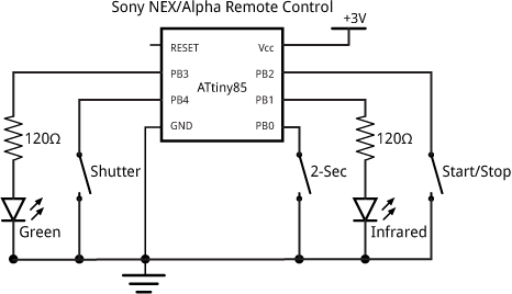
Circuit for the Sony NEX/Alpha three-button remote control.
The whole circuit was built on a SparkFun prototyping board [2] available from Proto-PIC in the UK [3]. It's powered by a 3V lithium button cell.
Compiling the program
I compiled the program using the Arduino-Tiny core extension to the Arduino IDE [4]. Select the ATtiny85 @ 1 MHz (internal oscillator; BOD disabled) option on the Boards menu and choose Burn Bootloader to set the fuses appropriately using the Tiny AVR Programmer Board; see ATtiny-Based Beginner's Kit. Then upload the program to the ATtiny85.
Here's the whole Sony NEX/Alpha Remote Control program: Sony NEX/Alpha Remote Control Program.
- ^ Sony SIRC Protocol on SB-Projects.
- ^ SparkFun Solder-able Breadboard Mini on SparkFun.
- ^ Solder-able Breadboard Mini on Proto-PIC.
- ^ Arduino-Tiny core on Google Code.
blog comments powered by Disqus