100MHz Frequency Meter
16th March 2021
This project is a simple frequency meter capable of measuring frequencies up to 100MHz with an accuracy of 0.002%. Based on an ATtiny414, it demonstrates the use of Timer/Counter TCD0 and the Event System:
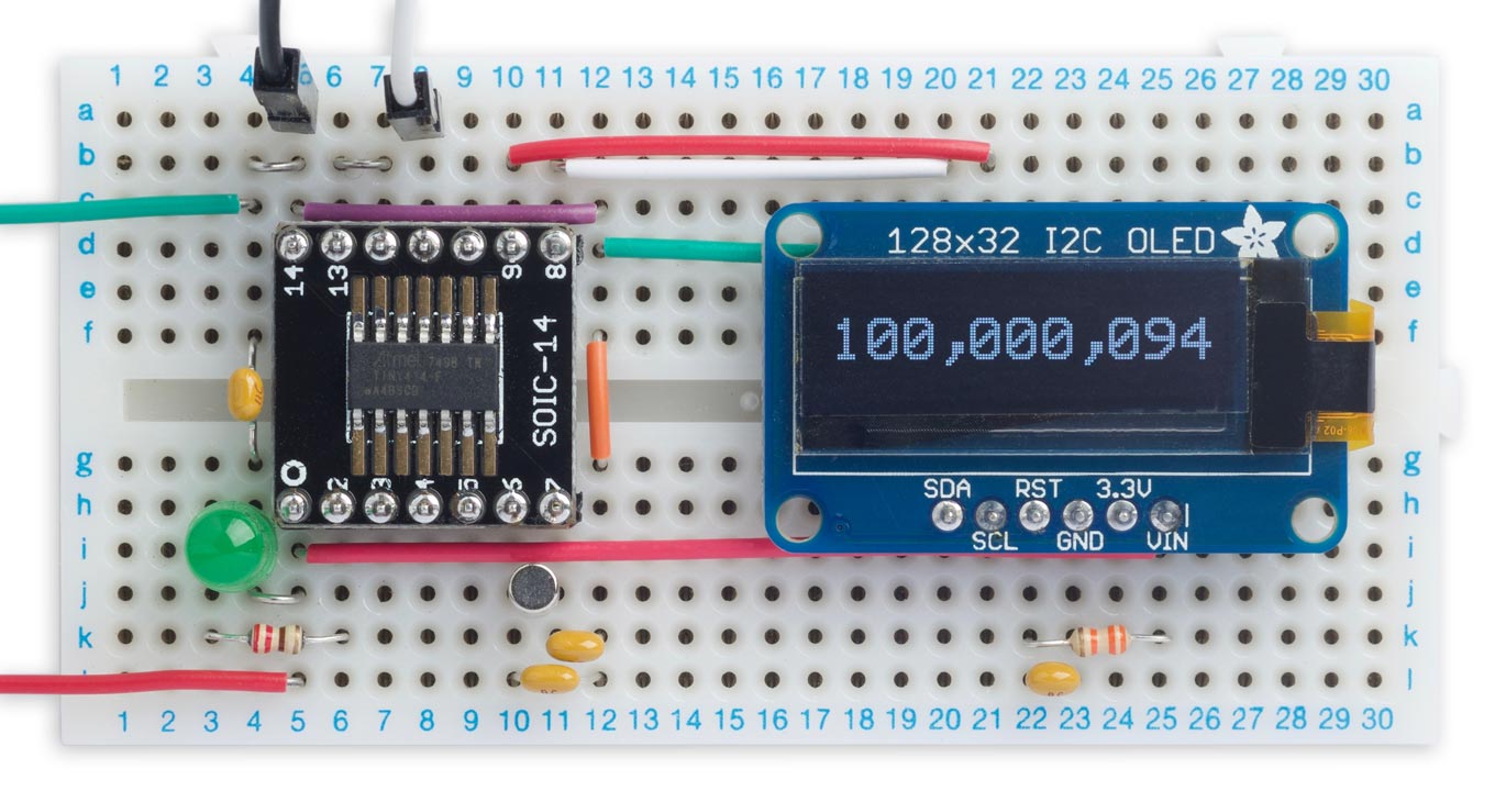
Frequency meter based on an ATtiny414 measuring an input of 100MHz.
Introduction
I recently wanted to design a frequency meter that would measure up to 100MHz, so you can use it to test processor clocks and crystals. There are many designs for microcontroller-based frequency meters on the web; after all, it's one of the applications that the timer/counters in most microcontrollers are designed for. However, most of them don't go as high as 100MHz because the microcontroller's own clock usually imposes an upper limit of half the clock frequency.
First attempt
My plan was to use the Real-Time Clock peripheral, clocked by a 32.768kHz crystal, to generate a 1Hz interrupt. A second timer/counter, clocked by the frequency being measured, would then count the number of cycles in this one-second interval. The result would simply be the frequency, in Hz.
For my first prototype I used Timer/Counter TCB0 clocked from an input pin, with the capture triggered by the 1Hz from the Real-Time Clock peripheral. I confirmed that I could only measure up to half the clock frequency, or 10MHz, so I'd need a four stage prescaler to divide the 100MHz input frequency by 16 to bring it within the range I could measure. This led to me experimenting with using the CCL as a prescaler, which I wrote about in the earlier article Frequency Divider Using CCL.
Using Timer/Counter TCD0
Just on the off-chance I thought about trying Timer/Counter TCD0. This is a 12-bit device, but unlike most other timer/counters it's asynchronous; in other words, it works independently of the processor clock.
TCD0 is primarily designed for waveform generation in applications such as motor control, and I don't pretend to understand most of its features, but it seemed that it should be possible to get it to capture the counter value under control from the Real-Time Clock.
It turned out that I could clock TCD0 at well over 100MHz, which would allow me to design this really simple frequency meter with the range I was looking for, without needing a prescaler.
Using the Event System
I could have used the Real-Time Clock to generate an interrupt every second, and then capture the count from Timer/Counter TCD0 in the interrupt service routine. However, the recent AVR processors provide an Event System which provides a better way of doing this. You can generate an internal signal from the Real-Time Clock, and use this to trigger the capture directly. The advantage is that there's none of the overhead of calling an interrupt service routine, so the response is virtually instantaneous.
Choice of microcontroller
Microchip now have three new ranges of AVR microcontrollers: the ATtiny 0-, 1-, and 2-series, the ATmega 0-series, and the AVR DA- and DB-series. They all have similar peripherals, so I could have chosen, for example, the ATtiny414, ATmega4809, or AVR128DA28, all of which can use an external 32.768kHz crystal for timing, and which include timer/counter TCD0. I tested a first version of the circuit with an AVR128DA28, but for the final version I chose the ATtiny414 because it has a more compact package, and I didn't need the extra I/O lines.
I had the events working with the AVR128DA28, but then after switching to the ATtiny414 they no longer seemed to work, and the problem turned out to be the different terminology used on the earlier processors. I'm grateful to user kabasan on AVR Freaks for helping me out. If you want to learn about using the Event System I recommend starting with the AVR DA- or DB-series, which have more logical terminology.
Note, don't confuse the ATtiny 1-series ATtiny414, released in 2020, with the older ATtiny441 which was released in 2014 as an enhanced version of the older ATtiny44.
Measuring crystals
I thought it would be useful to provide a crystal oscillator, to allow you to use the frequency meter to measure the resonant frequency of a crystal. One possible crystal oscillator design uses the Texas instruments unbuffered CMOS inverter LVC1GU04 and a few other components [1]:
I thought about whether it would be possible to create an inverter on the ATtiny414 using the Event System, as follows:
- Define PA2 as an event output, EVOUT0. This was the only choice, as the other event output, EVOUT1, is on the same pin as TOSC2 used by the RTC crystal oscillator.
- Define PA1 as an asynchronous event generator on channel 0. Any pin on PORTA would have been suitable.
- Configure PA1 to invert the input.
The inverter output, PA2, is then connected to the input to the frequency meter, EXTCLK on PA3.
In practice I found this worked perfectly on my prototype, without any additional components, with a range of crystals from 2MHz up to 25MHz. However, the capacitance of the breadboard might have been critical in getting the crystal to oscillate, so if you're designing a PCB for this circuit I recommend including spaces for the passive components in case they are needed.
The circuit
Here's the circuit of the 100MHz Frequency Meter, using a similar layout to the circuit on the prototyping board:
Circuit of the 100MHz Frequency Meter using an ATtiny414.
The display is an OLED 128x32 I2C display module using the SSD1306 driver [2]. In the prototype I used an Adafruit display [3] but you could also an equivalent display from AliExpress [4]. The 33kΩ resistor and 0.1µF capacitor ensure that the display is reset correctly when power is first applied, although you may not need them.
The crystal I used is a 32.768kHz cylindrical clock crystal with an accuracy of 20ppm and a load capacitance of 12.5pF [5]. To calculate the capacitor values I used the formula C = 2(CL - CS), where CL is the load capacitance 12.5pF, and CS is the stray capacitance which is probably as high as 5pF on the breadboard, giving C=15pF. On a PCB the stray capacitance would probably be 2.5pF.
The processor is an ATtiny414 in a 14-pin SOIC package [6] which I mounted on a breakout board; Adafruit provide a suitable one [7]. The project would work equally well with the larger memory ATtiny814 or ATtiny1614, but it won't work with the ATtiny404 as this doesn't support an external crystal on the RTC.
Using the frequency meter
Measuring frequency
To measure the frequency of a signal connect it between In and GND on the circuit. With a 3.3V supply the frequency meter worked up to about 105MHz, and increasing the supply voltage to 5V increased the upper limit to 110MHz.
Measuring a crystal
To measure a crystal connect it between the Xtal and In terminals on the circuit:
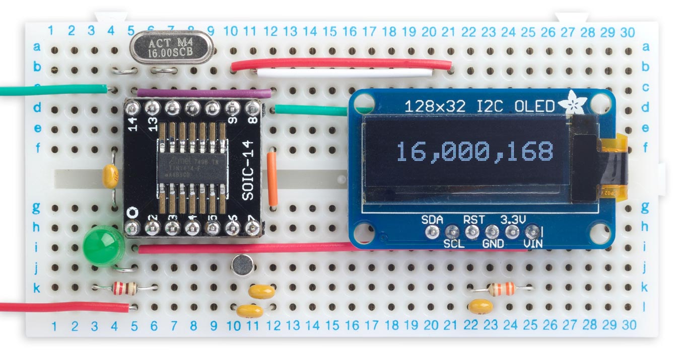
Measuring a 16MHz crystal with the frequency meter.
The program
Writing code for the ATtiny414
When writing code for the ATtiny414, and its peripherals, I found it useful to refer to the document AVR1000b: Getting Started with Writing C-Code for AVR MCUs. Also, when trying to guess what symbol to use for particular register settings it's useful to look through the file iotn414.h, which you can find in the megaTinyCore installation on your computer.
The OLED display
The display interface uses the same routines as many of my earlier projects, such as Tiny Function Generator, which used a similar I2C OLED display. Text is plotted on the display using a 6x8 pixel character set, but at double the scale to give an effective character size of 12x16 pixels, using the smoothing routine I described in Smooth Big Text.
Note that on the ATtiny414 in megaTinyCore the I2C buffer is only 16 bytes, to save RAM, so I had to modify the ClearDisplay() and PlotChar() routines to send the data in smaller batches.
I modified the PlotInt() routine to plot commas between each set of three digits, for readability.
Real-Time Clock
Setting up the RTC to use an external crystal is more complicated than you might expect, because the Clock Controller is protected from accidental change by Configuration Change Protection (CCP), so before each change you have to enable the action first. Fortunately there's an application note that explains how to do this, and my code is based on one of the examples in that note [8].
Timer/Counter TCD0
Timer/Counter TCD0 is set up to count up from 0 to 0xFFF, and capture the counter value to the CAPTUREB register when it receives an event B. It is set up to generate interrupts on the capture event, and when the counter overflows, and it's clocked from an external signal on the EXTCLK pin, PA3:
void TCDSetup () {
  TCD0.CTRLB = TCD_WGMODE_ONERAMP_gc;               // Set one ramp waveform mode
  TCD0.CMPBCLR = 0xFFF;                             // Count up to maximum
  TCD0.INPUTCTRLB = TCD_INPUTMODE_EDGETRIG_gc;      // Capture and reset counter
  TCD0.EVCTRLB = TCD_CFG_ASYNC_gc | TCD_ACTION_bm | TCD_TRIGEI_bm; // Enable event
  TCD0.INTCTRL = TCD_OVF_bm | TCD_TRIGB_bm;         // Enable interrupts

  // Ensure ENRDY bit is set
  while(!(TCD0.STATUS & TCD_ENRDY_bm));

  // External clock, no prescaler, enable timer
  TCD0.CTRLA = TCD_CLKSEL_EXTCLK_gc | TCD_CNTPRES_DIV1_gc | TCD_ENABLE_bm;
}
The overflow interrupt service routine simply increments a counter MSbyte for the high part of the frequency value:
ISR (TCD0_OVF_vect) {
  TCD0.INTFLAGS = TCD_OVF_bm;                       // Clear overflow interrupt flag
  MSByte++;
}
The capture interrupt service routine reads the capture register, and combines it with MSbyte to create the Counter value.
ISR (TCD0_TRIG_vect) {
  PORTA.IN = PIN4_bm;                               // Toggle LED on
  TCD0.INTFLAGS = TCD_TRIGB_bm;                     // Clear capture interrupt flag
  Counter = TCD0.CAPTUREB;
  Counter = (uint32_t)MSByte<<12 | Counter;
  MSByte = 0;
  Ready = true;
  PORTA.IN = PIN4_bm;                               // Toggle LED off
  TCD0.INTFLAGS = TCD_OVF_bm;                       // Clear overflow interrupt flag
}
It also flashes an LED to show when captures take place. You could leave the LED out if you don't want this feature.
The events
To use the events we need to set up the RTC overflow to generate event channel 1, and TCD0 to use the event to perform a capture:
void EvsysSetup (void) {
  EVSYS.ASYNCCH1 = EVSYS_ASYNCCH1_RTC_OVF_gc;       // Event generated from RTC OVF
  EVSYS.ASYNCUSER7 = EVSYS_ASYNCUSER7_ASYNCCH1_gc;  // Event causes a TCD0 capture

  EVSYS.ASYNCCH0 = EVSYS_ASYNCCH0_PORTA_PIN1_gc;    // PA1 is an event generator
  EVSYS.ASYNCUSER8 = EVSYS_ASYNCUSER8_ASYNCCH0_gc;  // ASYNCUSER8 is EVOUT0 (PA2)
  PORTMUX.CTRLA = PORTMUX_EVOUT0_bm;                // Enable EVOUT0
  PORTA.PIN1CTRL = PORT_INVEN_bm;                   // Invert input
}
Event channel 0 is used to create an inverter between PA1 and PA2 to act as a crystal oscillator, as described above.
Main loop
The main loop waits for the global variable Ready to be set, indicating that a capture has occurred. It then copies the Counter value to temp, with interrupts disabled to avoid the possibility that the value of Counter is changed by the interrupt service routine while it's being displayed:
void loop() {
  uint32_t temp;
  unsigned long start = millis();
  while (!Ready) {
    if (millis() - start > 1000) {
      Counter = 0;
      break;
    }
  }
  Ready = false;
  cli(); temp = Counter; sei();
  PlotInt(temp, 1, 0);
}
When there's no input signal Timer/Counter TCD0 isn't clocked, and the Counter value is never updated. To check for this situation there's a one-second timeout which sets Counter to zero if Ready hasn't been set. The value of zero is displayed as three dashes by the PlotInt() routine.
Accuracy
To test this project I was going to need to generate accurate signals of up to 100MHz, but I don't own a signal generator capable of generating these frequencies. My earlier project Programmable Signal Generator is only accurate to about 1.1%, so not really a good enough test for this project, and its upper limit is 68MHz. I therefore bought Adafruit's Si5351A Clock Generator Breakout Board [9] which you can program via I2C to generate from 8kHz to 160MHz (there's also a version on Banggood [10]). To drive it I used Jason Milldrum's excellent Si5351 Library [11], running on an Arduino Uno.
The accuracy of the meter primarily depends on the accuracy of the 32.768kHz crystal used to generate the 1Hz sampling signal. I used a cylindrical clock crystal which has a stated accuracy of 20ppm; this sounds good until you calculate that this is equivalent to ±2000Hz with a 100MHz input signal. In practice I found that its accuracy was generally about a factor of 5 or 10 better than this.
Compiling the program
Compile the program using Spence Konde's megaTiny Core on GitHub. Choose the ATtiny1614/1604/814/804/441/404/241/204 option under the megaTinyCore heading on the Board menu. Check that the subsequent options are set as follows (ignore any other options):
Chip: "ATtiny414"
Clock: "20 MHz Internal"
millis()/micros(): "TCA0 (default on 0-series)"
Then upload the program to the ATtiny414 using a UPDI programmer. The megaTinyCore now supports the following two options:
- Make a UPDI programmer from an Arduino Uno, or other ATmega328P-based board, as described in Make UPDI Programmer, and set the Programmer option to "jtag2updi".
- Use a USB to Serial board, such as the SparkFun FTDI Basic board [12], connect TX to the UPDI pin via a 4.7kΩ resistor, connect RX directly to the UPDI pin, and set the Programmer option to "Serial port and 4.7k (pyupdi style)".
You can ignore the error "Cannot locate flash and boot memories in description".
If you get the error:
(.text+0x0): multiple definition of `__vector_15'
it means you haven't set the millis()/micros() option to TCA0 as described above.
Here's the whole 100MHz Frequency Meter program: 100MHz Frequency Meter Program.
Further suggestions
Front end
This circuit assumes that your input frequency is a logic-level square wave. In a practical workbench frequency meter you would ideally have an analogue front end to drive the counter, with input protection. One option would be a module based on a TLV3501 high speed comparator.
Period measurement
The pulse-counting technique used by this meter is most accurate for high frequencies. You could combine this approach with interval measurement for low frequencies, as described in my earlier article Frequency Probe.
- ^ Use of the CMOS Unbuffered Inverter in Oscillator Circuits on ti.com.
- ^ SSD1306 datasheet on Adafruit.
- ^ Monochrome 128x32 I2C OLED graphic display on Adafruit.
- ^ 0.91 inch 128x32 I2C Serial OLED LCD Display Module on AliExpress.
- ^ AB38T-32.768kHz on Farnell.
- ^ AVR128DA28-I/SP on Mouser.co.uk.
- ^ SMT Breakout PCB for SOIC-14 or TSSOP-14 on Adafruit.
- ^ TB3213 Getting Started with RTC on Microchip.
- ^ Adafruit Si5351A Clock Generator Breakout Board on Adafruit.
- ^ Si5351A Clock Generator Signal Generator on Banggood.
- ^ Si5351 Library for Arduino on GitHub.
- ^ SparkFun FTDI Basic Breakout - 5V on Sparkfun.
blog comments powered by Disqus