Harmonic Function Generator
4th April 2018
This article describes a simple function generator based on an ATtiny85 which allows you to generate a virtually unlimited number of waveforms using additive harmonic synthesis, by specifying the amplitude of each of the waveform's harmonics:
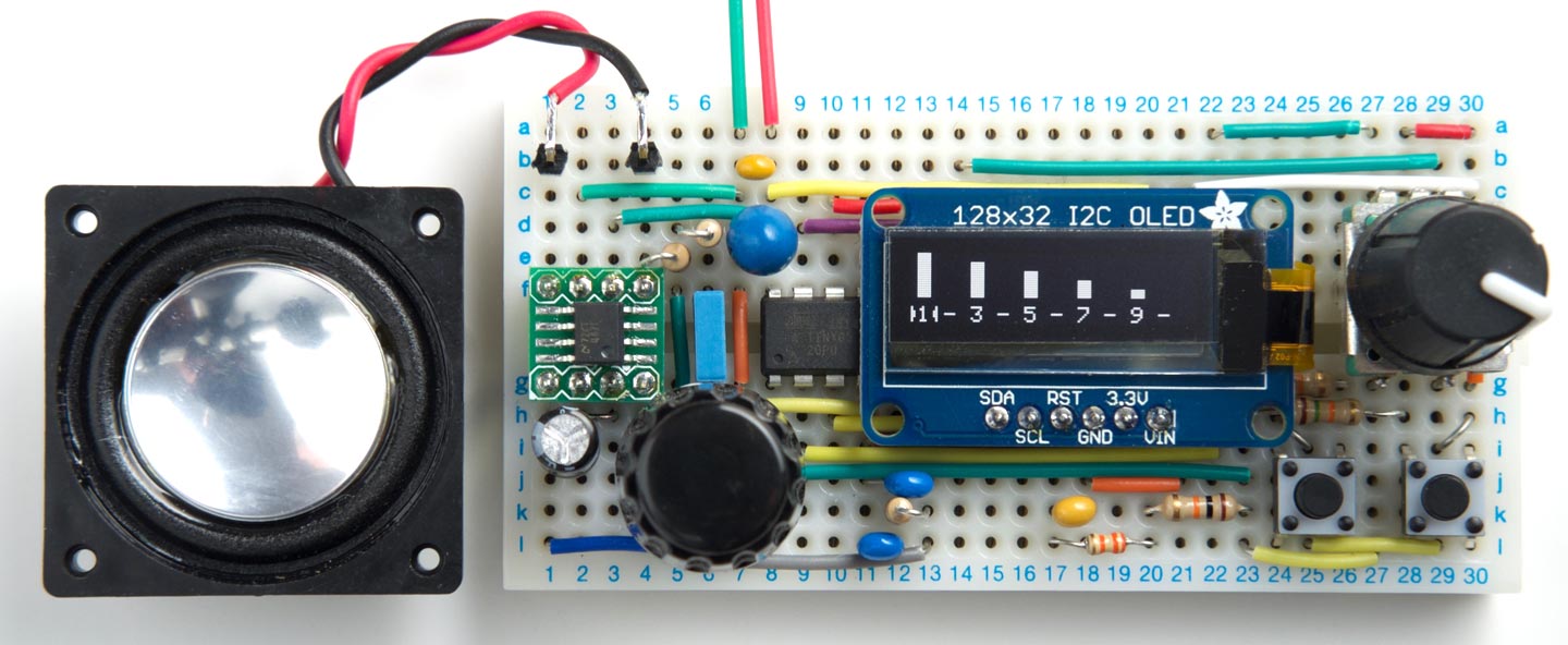
Harmonic Function Generator based on an ATtiny85 allows you to design a waveform by adding harmonics.
It includes a volume control, audio amplifier, and loudspeaker so you can hear the waveforms. It's not only a useful waveform generator, but also a good introduction to the composition of musical notes.
Introduction
Unlike most of my other projects on Technoblogy I didn't originally set out to design this. I got the idea after working out a way to add a sine wave to my original Tiny Function Generator project, realising I could take this one step further and use the same technique to allow you to generate arbitrary waveforms by specifying the amplitude of each of their harmonics.
Because I wanted to hear the effect on a waveform of modifying individual harmonics, I also added an audio amplifier and volume control to the design so it will drive a loudspeaker.
How it works
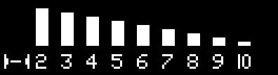
To design a waveform you press the rotary encoder button to go into design mode, and the display shows a representation of the amplitude of each of the first ten harmonics:
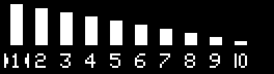
You can then use the left and right push buttons to select a harmonic; the currently selected harmonic is shown by an arrow cursor. You can then turn the rotary encoder to set the amplitude of that harmonic. The amplitude is shown by the height of the bar, and the number below the bar.
The first element is the first harmonic, or fundamental frequency; the second element is the second harmonic, at twice the fundamental frequency, and so on.
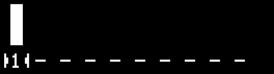
Setting a harmonic to zero means that it is missing, and the amplitude is displayed with a dash. Setting it to an integer n means that the harmonic is present, with an amplitude of 1/n. For example, this waveform has just the first and third harmonics, and the third harmonic is 1/3 of the amplitude:

Having defined a waveform you can then press the rotary encoder button to output the waveform you have defined, with its frequency adjustable over the range 1Hz to 1500Hz with a resolution of 1Hz, and the display shows the frequency:

Examples
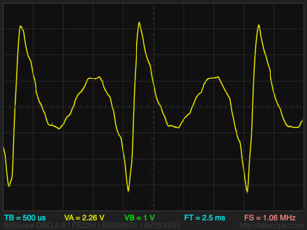
Here are some examples of waveforms you can generate with the Harmonic Function Generator, together with oscilloscope traces of the output measured at the Line Output [1]:
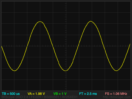
Sine wave
If you set all the harmonics to zero except the first, or fundamental, you get a simple sine wave:
Here's the waveform:
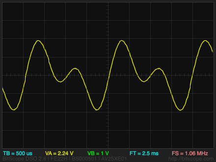
Two harmonics
Adding the second harmonic at the same level gives a waveform with two harmonics:

Here's the waveform:
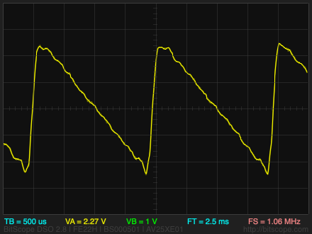
Sawtooth
If you add together the first ten harmonics with an amplitude inversely proportional to the number of the harmonic you get a sawtooth wave:
Here's the waveform:
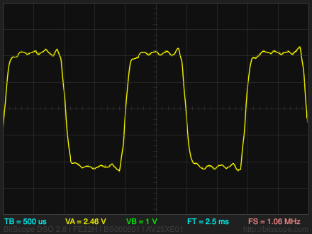
Square
If you add together the odd harmonics with an amplitude inversely proportional to the number of the harmonic you get an approximation to a square wave:

Here's the waveform:
Missing fundamental
Finally, here is an interesting waveform; it contains no fundamental frequency. It can be used to demonstrate the auditory illusion of the "Missing Fundamental" [2]:
If you listen to this waveform you can clearly hear a note at the fundamental frequency even though there is no energy at that frequency.
The circuit
Here's the circuit of the Harmonic Function Generator:
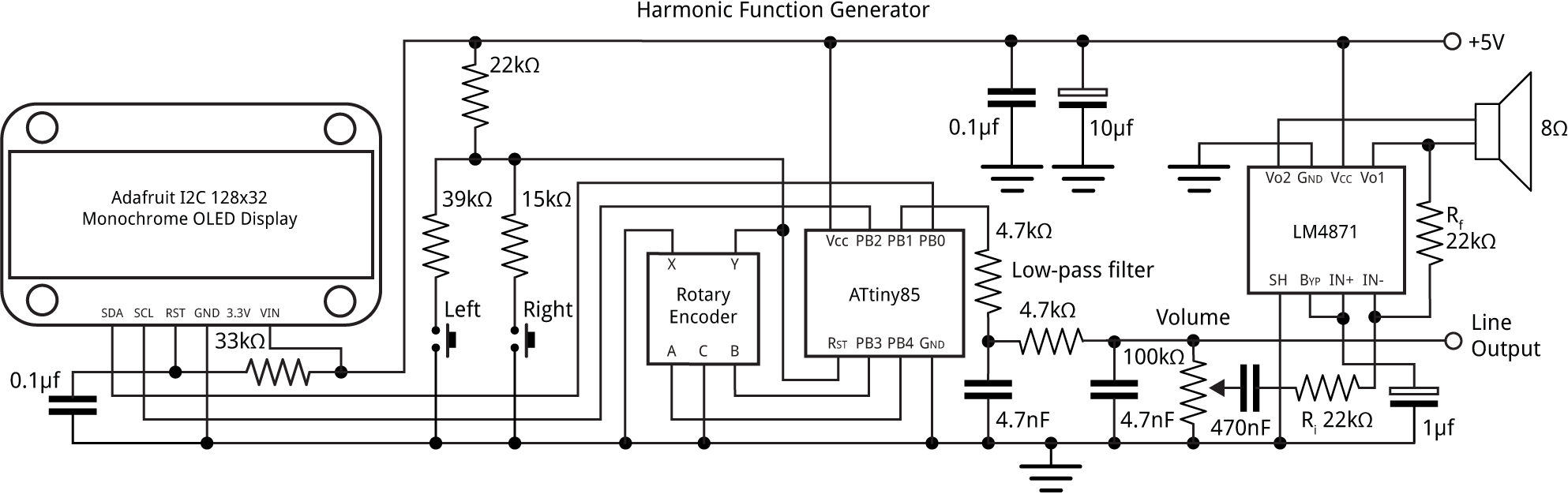
Circuit of the ATtiny85-based Harmonic Function Generator.
The circuit is based on my earlier Tiny Function Generator, with the addition of the Left and Right push buttons, and the audio amplifier on the output.
Push buttons
For this application I needed two push buttons to allow you to select which of the harmonics to edit with the rotary encoder, and there were no I/O pins left on the ATtiny85. Fortunately you can use the reset line as an analogue input, provided you never take the voltage below about 0.3 Vcc, or 1.5V which would reset the chip. The push buttons are connected to potential dividers that generate 3V and 4V respectively, so there's plenty of safety margin for variations in the resistor values.
Audio amplifier
For this circuit I decided it would be nice if it could drive a loudspeaker directly, so you can hear the result of modifying the harmonics in a waveform. After a bit of research I chose the LM4871 from Texas Instruments [3] which provides 1.5W into an 8Ω loudspeaker (the LM4890 is very similar). It's a BTL (bridge-tied load) design, avoiding the need for an output capacitor between the amplifier and the loudspeaker. It's only available in an SMD package so I used a breakout board [4] to make it compatible with the prototyping board. The voltage gain is 2 x Rf/Ri, or 2.
The program
Adding the harmonics
The program works by calculating the sine waveform in a 256-byte array, and this is then used by the DDS to generate the sine wave output.
The waveform is stored in a 256-byte array:
int8_t Waveform[256];
Here's the routine CalculateWave() to calculate a user waveform:
void CalculateWave () {
  int scale = 0;
  // Calculate scale factor
  for (int n=1; n<=Harmonics; n++) {
    int h = Harmonic[n-1];
    if (h == 1) scale = scale + 2048/h;
    else if (h > 1) scale = scale + 2048/(h+1);
  }
  scale = scale>>5;
  for (int i=0; i<256; i++) Waveform[i] = 0;
  for (int h=1; h<=Harmonics; h++) {
    int X=0, Y=8186;
    for (int i=0; i<256; i++) {
      for (int j=0; j<h; j++) {
        X = X + (Y*4)/163;
        Y = Y - (X*4)/163;
      }
      int value = X/scale;
      if (Harmonic[h-1]) Waveform[i] = Waveform[i] + value/Harmonic[h-1];
    }
  }
}
When we sum the sine waves for each of the harmonics it's important we don't overflow the 8-bit integers in the Waveform array. Ideally we would sum the harmonics to a higher precision, such as 16-bit integers, and then normalise them according to the largest value in the array; unfortunately there isn't enough RAM to do this. The solution is to calculate a scale factor based on an estimate of what the maximum amplitude of the sum of the harmonics will be, and then scale everything by this. It took me a bit of trial and error to get to the best way of calculating this.
The Waveform array is zeroed. Then for each of the harmonics the routine steps through the 256 points of a single cycle of a sine wave, adding the values into the Waveform array.
The key part of this routine is the loop:
for (int i=0; i<256; i++) {
  X = X + (Y*4)/163;
  Y = Y - (X*4)/163;
}
which uses the Minsky circle algorithm to calculate the 256 points in a sine wave, without needing floating point or trig functions. The value 4/163 is a close approximation to (2*π)/256. For the nth harmonic the routine takes n steps around this loop for each sample.
User interface
A global variable Mode is used to specify which mode you are in; true represents design mode, and false represents waveform generation mode. Pressing the rotary encoder button toggles between modes.
In design mode the analogue inputs from the push buttons are read in loop() and these move the cursor left or right. The rotary encoder calls ChangeHarmonic() which changes the currently selected harmonic.
In waveform generation mode the rotary encoder calls ChangeFreq(), which changes the output frequency. In this version of the program I've limited the upper frequency to 1500Hz because above that anti-aliasing effects become noticeable.
Graphics routines
Two additional graphics routines are used in design mode: PlotBar() plots the bar representing the value of a specified harmonic, and PlotCursor() draws the cursor showing which bar is currently selected.
Compiling the program
I compiled the program using Spence Konde's ATTiny Core [5]. Choose the ATtiny25/45/85 option under the ATtinyCore heading on the Board menu. Then choose Timer 1 Clock: CPU, B.O.D. Disabled, ATtiny85, 8 MHz (internal) from the subsequent menus. Choose Burn Bootloader to set the fuses appropriately. Then upload the program using ISP (in-system programming); I used Sparkfun's Tiny AVR Programmer Board; see ATtiny-Based Beginner's Kit.
Here's the whole Harmonic Function Generator program: Harmonic Function Generator Program.
Further suggestions
As with my Tiny Function Generator the accuracy of the frequency depends on the accuracy of the ATtiny85's internal 8MHz clock. To get the frequency as accurate as possible you can calibrate the internal clock using the OSCCAL register. See the original article for details of how to do this.
You could allow several sets of waveforms definitions to be stored in EEPROM, so you could select between them without needing to define the harmonics each time.
With a larger display, such as a 128x64 OLED display, after defining the harmonics you could display a plot of the waveform data to show the waveform you've created.
- ^ The oscilloscope traces were captured using a BitScope Micro BS05 Oscilloscope, available from Pimoroni in the UK.
- ^ Missing fundamental on Wikipedia.
- ^ LM4871 Datasheet on Texas Instruments.
- ^ HT SOIC to DIP Adapter 8-Pin on HobbyTronics.
- ^ ATTinyCore on GitHub.
blog comments powered by Disqus