Power Deliverer with Current Monitor
7th February 2023
This is an update to my earlier Power Deliverer project to add a current monitor that gives a continuous display of the current consumption:
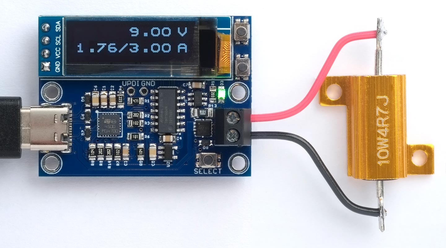
The Power Deliverer board, based on an STUSB4500 and an ATtiny1604 microcontroller,
showing the current consumption from a USB-C power adapter.
The Power Deliverer allows you to use a USB-C power adapter as a power supply with a range of fixed voltages. It displays a list of the voltages and currents available from the adapter and allows you to select one. Once you've selected a voltage option, it monitors the current consumption and shows it on the display.
It's based on an STUSB4500 integrated circuit, an ATtiny1604 microcontroller, and an INA181A2 current monitor, and it displays the information on a 128x32 OLED display.
Introduction
In my original Power Deliverer project I suggested a possible extension which would add a current sensor, to allow you to show an active display of the current being drawn by the load. I suggested using either an I2C sensor such as the INA219, or an analogue sensor such as the INA199 which you could read with an analogue input on the ATtiny1604.
I decided to go ahead and do this, and chose the Texas Instruments INA181 current sensor [1] because it's relatively cheap and, more importantly, I was able to find it in stock. The additional components fit on a PCB of the same size as the original one.
Current monitor
The current monitor works by measuring the small voltage drop across a current-sensing resistor, between the positive voltage output and the load, so it's referred to as a "high-side" current monitor. Because the positive rail might be up to 20V it's too high to read directly with an analogue input on the microcontroller, so you would need two matched high-precision voltage dividers. A simpler solution is to use an analogue sensor such as the INA181A2.
The maximum current the Power Deliverer might carry is 5A. A 0.1Ω sense resistor would drop 0.5V, which is a significant voltage drop, and at that current it will dissipate 2.5W, which means it will run pretty hot. A better choice is a 0.01Ω sense resistor which will only drop 0.05V and dissipate 0.25W.
The INA181A2 I chose has a gain of 50V/V. This allows us to use a voltage reference of VCC, or 3.3V, to get a full scale reading of 1024 with 6.6A current.
How it works
When you connect my Power Deliverer board to a USB-C charger with Power Delivery it displays a menu of the available voltages and their current capabilities, called power profiles, up to a maximum of 20V at 5A:
The power profiles from the AUKEY Omnia Mix 3 90W charger.
You can highlight a power profile with the cursor, and then pressing the Select button will select this voltage on the output terminals. The display then shows the currently selected voltage, the actual output current, and the maximum available current:

The current display for a selected power profile.
A green LED also lights up to show that the output is active.
As before, if the charger doesn't support Power Delivery the display shows:

Display if Power Delivery isn't supported.
IMPORTANT: As I said in the earlier article, this project is only intended for hobby use, and is not an end-user product. I haven't tested it to make sure that it meets any regulatory requirements, including interference and safety, and it's possible that a programming fault could potentially cause it to output a higher voltage than selected. Please do not use it to power valuable equipment!
The circuit
Here's the updated circuit of the Power Deliverer with the current monitor:
The circuit of the updated Power Deliverer board, based on an STUSB4500, an ATtiny1604 microcontroller, and an INA181A2 current monitor.
Here's an updated parts list, with the additional components needed for the current monitor marked with an asterisk:
► Parts list
Construction
See the original article for the construction details: Power Deliverer - Construction.
The program
The main change to the program to add current monitoring is the routine DisplaySelected(), which is called to display the profile selected from the list of profiles:
void DisplaySelected () {
  ButtonsOff();
  SelectPDO(Cursor);
  UpdatePDONumber(2);                                 // Turn on selected voltage
  SendSoftReset();
  ClearBuf();
  Scale = 2;
  PlotVal(PDObject[Cursor].voltage, 0, 8, true, true);
  PlotVal(PDObject[Cursor].current, 3, 10, false, true);
  PlotChar(Slash, 3, 8);
  SelectPressed = false;
  do {
    uint16_t current = (analogRead(Sense) * 29)/45;
    PlotVal(current, 3, 0, false, false);
    UpdateScreen();
    unsigned long now = millis();
    while (millis() - now < 1000);                    // Update once a second
  } while (!SelectPressed);                           // Wait for Select button
}
This displays the profile's voltage and maximum current. It then samples the analogue input every 500ms to read the output from the current sense amplifier, and displays that too.
Power delivery supports a maximum current of 5A; this gives a voltage of 50mV across the 0.01Ω sense resistor. The INA181A2 has a gain of 50V/V, so this gives a voltage of 2.5V at the SENSE ADC input. The default ADC reference is VCC, or 3.3V, so a reading of 1024 corresponds to 3.3V.
We therefore need to multiply the reading by (3.3/2.5)x500/1024 to give the current in units of 10mA. A close approximation to this is 29/45, avoiding overflow in the 16-bit arithmetic. The maximum current that can be displayed is 6.6A, giving a bit of a margin above the maximum theoretical current of 5A.
Compiling the program
For details of compiling and uploading the program see: Power Deliverer - Compiling the program.
Resources
The Power Deliverer program uses my compact I2C library, TinyI2C (see TinyI2C on GitHub).
Here's the Power Deliverer with Current Monitor program: Power Deliverer Current Program.
Get the Eagle files for the updated PCB on GitHub here: https://github.com/technoblogy/power-deliverer.
Or order boards from OSH Park here: Power Deliverer with Current Monitor.
Or order boards from PCBWay here: Power Deliverer with Current Monitor.
- ^ INAX181 datasheet on TI.com.
blog comments powered by Disqus