UPDI Programmer Stick
30th October 2019
This is a USB-stick sized UPDI programmer, for programming Microchip's new 0-series and 1-series ATtiny chips from the Arduino IDE:
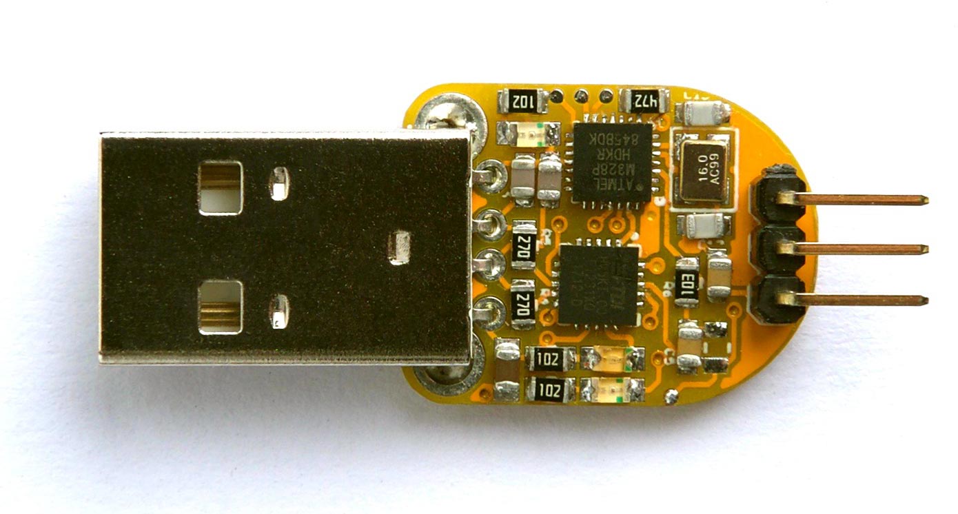
UPDI Programmer Stick based on an ATmega328P.
It's based on an ATmega328P, and is essentially an Arduino Uno on a USB stick, so you also could use it as a mini-sized Arduino Uno.
Introduction
Starting in 2016 with the ATtiny87 and ATtiny167 Microchip started releasing a new series of ATtiny chips called the ATtiny 1-series, followed in 2018 by a lower cost range called ATtiny 0-series. They are intended as successors to the earlier ATtiny chips, such as the ATtiny85 and ATtiny84. I reviewed the range in an earlier article: Getting Started with the New ATtiny Chips.
A new Arduino core has been developed for the new ATtiny chips by Spence Konde and his collaborators, called megaTinyCore [1]. The new chips also use a new programming method called UPDI, and on his GitHub repository Spence Konde has described how to make an UPDI programmer by installing ElTangas's jtag2updi program on an Arduino Uno, or other ATmega328-based Arduino board [2].
I thought it would be nice to have a compact programmer for these devices, and so designed this ATmega328-based controller on a small USB stick that can plug straight into a computer's USB socket.
In addition to the three pins needed for UPDI programming, the board brings the ISP pins to pads on the edge of the board to allow you to install a bootloader.
The circuit
Here's the circuit of the UPDI Programmer Stick, which roughly reflects the layout of the PCB:
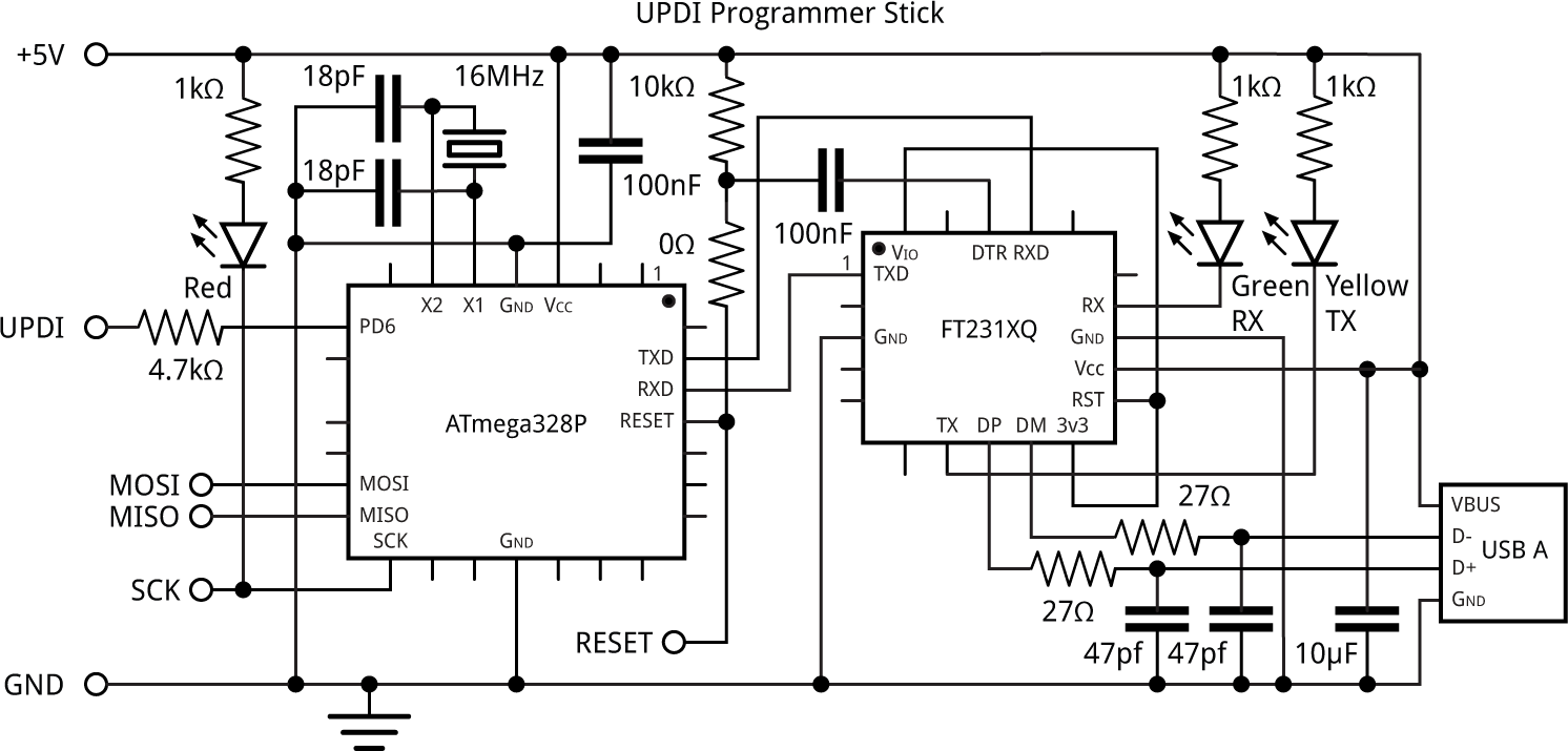
Circuit of the UPDI Programmer Stick.
The USB interface is an FTDI FT231XQ-R, in a small 20-pin QFN package [3] and the ATmega328P is in a 28-pin QFN package [4].
The crystal is a 16MHz 3.2 x 2.5mm SMD type that needs 18pF capacitors, and all the capacitors, resistors, and LEDs are 0805 size.
The USB plug is a through-hole type, available from SparkFun [5].
For the three-pin header I used a right-angle header plug, but you could use a header socket, connect wires directly, or use any suitable 0.1" pitch three-way socket.
If you want to use the board as a UPDI programmer don't fit the 0Ω resistor, but put a wire link in its place that you can easily remove later. If you want to use the board as a mini Arduino Uno fit the 0Ω resistor.
I designed a PCB in Eagle and ordered boards from PCBWay. See the end of the article for links to download the board files or order a board.
► Parts list
Construction
Because of the two QFN packages I wouldn't recommend attempting to build this PCB unless you've got experience of SMD work, and have access to a hot plate or hot air gun.
My method for soldering the QFN packages was as follows. With the help of an illuminated magnifying glass I put a small blob of solder paste on each pad, and then positioned the packages using a pair of tweezers. I then heated the packages with a Youyue 858D+ hot air gun at 250°C until I could see molten solder glistening around the border of each package. I fitted the remaining SMD components in the same way, and finally soldered the header and USB plug using a conventional soldering iron. Fortunately the board worked first time.
The components are quite tightly packed on the board, so make sure none of them end up touching. If necessary, reheat the board and move them apart slightly.
Installing the software
Installing a bootloader
The first step is to install a bootloader in the flash memory of the ATmega328, using an ISP programmer, so that you can subsequently use the USB port for uploading programs. You don't need to have the USB plug fitted to the board for this step.
- If you haven't already done so, solder a wire link in the position of the 0Ω resistor on the board. This connects the reset line to the processor.
- Solder wires to the MOSI, MISO, SCK, and RESET pads on the board, and connect these to header sockets that you can connect leads to:
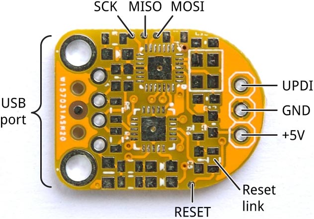
Connections for uploading a bootloader using ISP programming.
I recommend using very fine wires for the connections, so you don't inadvertently lift the pads off the PCB.
- Connect a 3-pin header to the three terminals at the top of the UPDI programmer PCB so you can use this to connect GND and 5V to the board.
- Connect an ISP programmer to the board via the six wires you have provided.
I used Sparkfun's Tiny AVR Programmer Board [6]. Alternatively you could use an Arduino Uno as a programmer as described in the Arduino sketch ArduinoISP in the Built-in Examples section on the Examples menu.
I recommend monitoring the current consumption when you first connect power to the board; anything above about 20mA is suspicious, and so disconnect power immediately, as it probably indicates a short or incorrect connection.
- In the Arduino IDE choose Arduino/Genuino Uno from the Arduino AVR Boards section on the Boards menu, and set the Programmer to USBtinyISP (or ArduinoISP if you're using an Arduino Uno).
- Choose Burn Bootloader to upload the bootloader to the board.
If that succeeds your board is probably working OK, and you have successfully installed the bootloader. If it fails, check your connections, and look for any possible shorts on the PCB.
Checking the USB interface
- If you haven't already done so, fit the USB plug to the board, making sure you fit it to the top (component) side of the board.
- Plug the UPDI Programmer Stick into your computer, and check that the USB port appears on the Arduino IDE's Port menu.
As an optional additional check you can now try uploading the Blink example program to the board via the USB port using the Upload option on the Sketch menu. If all is well the red LED should flash on the UPDI Programmer Stick. If this fails, make sure you've uploaded a bootloader as described in the previous step.
If you just want to use the board as an Arduino Uno with a USB-stick form-factor you can stop here. Arduino Pin 6 is available on the header; you can use this as a digital input/output or an analogue (PWM) output.
Otherwise to use it as an UPDI programmer proceed to the next step.
Uploading the UPDI programmer
- Download the UPDI programmer sketch from: https://github.com/SpenceKonde/jtag2updi.
- Browse to the download location and open the jtag2updi folder.
- Open the jtag2updi.ino sketch and upload it to your UPDI programmer Stick.
The .ino file itself is empty; this is intentional - the actual code is contained in other files in the same folder.
- Remove the reset link you fitted earlier in the 0Ω resistor position on the board.
The UPDI Programmer Stick is now ready for use as a UPDI programmer.
Programming a 0-series or 1-series ATtiny chip
The procedure to program a device is as follows:
- Install Spence Konde's megaTinyCore in the Arduino IDE, as described in megaTinyCore Installation.
- In the Arduino IDE select the appropriate family from the megaTinyCore section of the Boards menu, and the appropriate part from the Chip menu.
- Select jtag2updi (megaTinyCore) from the Programmer menu.
- Connect the UPDI Programmer Stick to the chip you're programming, select its USB port from the Port menu, and select Upload.
The UPDI Programmer Stick includes a 4.7kΩ resistor in series with the UPID pin, so you don't need one on your target board.
For example, here I'm using the UPDI Programmer Stick to program an ATtiny412 on a mini breadboard with the Arduino Blink example program:
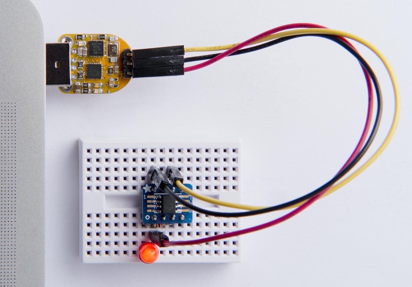
Programming an ATtiny412 with the Blink example program using the UPDI Programmer Stick.
Making a PCB
Get the Eagle files for the PCB from GitHub so you can make yourself a board, at: https://github.com/technoblogy/updi-programmer-stick.
Or order a board from PCBWay here: UPDI Programmer Stick.
Or order a board from OSH Park here: UPDI Programmer Stick.
- ^ megaTinyCore on GitHub.
- ^ Make UPDI Programmer on GitHub.
- ^ FT231Q-R on Farnell.
- ^ ATmega328P-MMH on Farnell.
- ^ USB Male Type A Connector on SparkFun.
- ^ Tiny AVR Programmer on SparkFun.
blog comments powered by Disqus