Tiny Machine-Code Monitor
18th July 2018
This project is a machine-code monitor that you program from a hexadecimal keypad using a simplified instruction set:
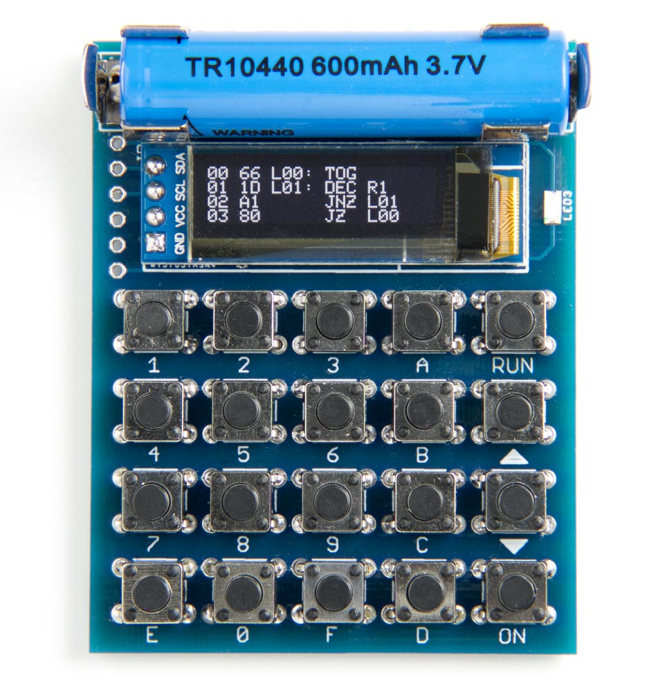
The Tiny Machine-Code Monitor, which you program using a simple instruction set.
It's a good project for learning about the fundamentals of machine code, and will also appeal to people who like programming challenges. The simplified machine code, called MINIL, is designed to be easy to learn and understand. It's similar to the Little Minion Computer [1] used in some universities to teach students about machine code. The same method could be used to emulate other simple processors, such as the SC/MP, 6800, 8080, or 6502.
Introduction
In the early days of microprocessors the only way a hobbyist or engineer could try out a chip was to get one of the manufacturer's evaluation boards that allowed you to program in machine code using a hexadecimal keypad and seven-segment displays. Some early examples were the National Semiconductor SC/MP kit, the Motorola D2 kit for the 6800 [2], and the KIM-1 board from MOS Technology Inc. for the 6502 [3]. Later some companies produced boards specifically aimed at hobbyists, such as the Science of Cambridge MK14 [4], and the Acorn System 1 [5].
Now that powerful processors are available at low cost beginners can go straight to programming in a high-level language such as Python on a board such as an ARM-based Arduino or BBC Micro Bit. However, I sometimes think that they are missing out on the fun and understanding to be gained from programming in assembler or machine code. After all, when running a high-level language program on one of today's advanced processors it is actually executing machine code at the lowest level, so it's useful to understand what this means.
One approach to building a machine-code monitor would be to use the machine code of the chip used to build it. However, even the simplest and cheapest chips available nowadays have quite complex instruction sets which would be daunting for a beginner. For example, the ATtiny chips have over 80 instructions, and the simplest chips you can still buy easily are 8051-based, with 44 instructions.
The second option would be to emulate one of the early processors which had much simpler instruction sets; there have been several boards based on emulations of the SC/MP or 6502, either using another processor, or an FPGA.
However both of these options would be quite daunting for a beginner; even the SC/MP and 6502 had many instructions and addressing modes, and using them would require a programming manual open alongside you at the bench.
No assembler required
With most microprocessors the hexadecimal operation codes, or opcodes, used for the instructions are arbitrary, and so it is difficult to remember what opcode you need to write for each instruction. Programmers therefore use assemblers, which allow you to use a mnemonic for each instruction. For example, in the 8051 the jump instruction is 0x73, but using the assembler you can write JMP instead.
I decided to base my machine-code monitor on a hypothetical processor called MINIL (MINiature Interpreted Language) that I developed some time ago [6]. It avoids the need for an assembler by having a very simple set of opcodes that are easy to remember. For example, the instructions to set one register to another are simply the two register numbers, so to set R3 to R4 (mnemonic MOV R3,R4), the opcode is 0x34.
Also, once you type in the opcode the Tiny Machine-Code Monitor displays the assembler statement alongside it on the display, allowing you to check that it's what you intended. Because you enter the opcodes in hexadecimal it avoids the need for a full alphanumeric keyboard, while giving you the advantage of seeing the assembler program on the display.
The MINIL instruction set
Overview
The MINIL instruction set consists of just 16 instructions. The instructions are all single byte, and there is no memory addressing; all operations are between the eight 16-bit registers, called R0 to R7. R0 is special, as it is one of the operands in the ADD, SUB, and LDC instructions; otherwise the registers are identical.
In the following descriptions all numbers are assumed to be in hexadecimal. Here's a summary of the instructions:
| Mnemonic | Op Code | Flags | Description |
| ADD Rx | xA | Z, C | Add Rx to R0 |
| BRK | 00 | Break | |
| CPY x | xC | Copy constant x into R0 | |
| DEC Rx | xD | Z, C | Decrement Rx |
| ENT Rx | xE | Enter Rx | |
| JZ address | 8a, 9a | Jump if zero | |
| JNZ address | Aa, Ba | Jump if non zero | |
| JC address | Ca, Da | Jump if carry set | |
| JSR address | Ea, Fa | Jump to subroutine | |
| MOV Rx,Ry | xy | Move Rx = Ry | |
| NOP | 11 | No operation | |
| PSH Rx | x8 | Push Rx onto stack | |
| POP Rx | x9 | Pop Rx from stack | |
| RTS | 77 | Return from subroutine | |
| SUB Rx | xB | Z, C | Subtract Rx from R0 |
| TOG | 66 | Toggle LED |
Rx and Ry are registers from R0 to R7
address is an absolute address from 00 to 1F
Z and C are the Zero and Carry flags.
The instruction set illustrates many of the features of more advanced processors. It's based on the instruction set I used for an earlier project, MINIL Machine-Code Monitor, with the addition of a few instructions to make it more flexible.
Sample program
The MINIL instruction set may be extremely primitive, but it can be used to write non-trivial programs; for example, here's a program to find the highest prime factor of any number up to 9999 in just 12 bytes!
00 1E  Factor:ENT R1
01 31  Not:   MOV R3,R1
02 23  New:   MOV R2,R3
03 2D  Fail:  DEC R2
04 01  Next:  MOV R0,R1
05 2B  Loop:  SUB R2
06 A3         JC Fail
07 C5         JNZ Loop
08 12         MOV R1,R2
09 2D         DEC R2
0A C1         JNZ Not
0B 3E  Done:  ENT R3
In this listing I've added some labels, such as Factor and Loop, to make the structure of the program clearer. These don't appear on the display.
For more example programs see MINIL Programs.
Instruction set groups
There are three main groups of instructions:
Moves

The MOV instructions copy the value in one register to another register (leaving the original unchanged). They consist of two hex digits, 0 to 7, specifying the destination and source registers.
Single register operations
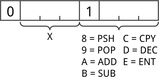
These all operate on a single register. The first hex digit is the register, 0 to 7, and the second hex digit specifies the operation. In most cases the second hex digit is a mnemonic for the instruction:
ADD (rA) - Adds the specified register to R0.
SUB (rB) - Subtracts the specified register from R0.
CPY (xC) - Copies a constant x, from 0 to 7, into R0.
DEC (rD) - Decrements the specified register by 1.
ENT (rE) - Enter number. It displays the contents of the specified register on the display. If RUN is pressed the program continues without altering the register's contents. Alternatively you can enter a number followed by RUN to put that into the register.
PSH (r8) - Pushes the specified register onto the stack.
POP (r9) - Pops the specified register from the stack.
Jumps
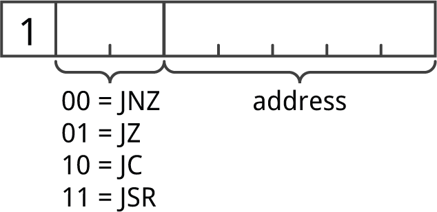
The four jump instructions take a 5-bit address, and jump to that absolute address. I chose to make the jumps absolute so it is easy to see where the destination of the instruction is.
JZ (jump if zero) instructions are in the range 80 to 9F, and jump if the result of the previous ADD, SUB, or DEC instruction was zero.
The JNZ (jump if non-zero) instructions are in the range A0 to BF, and jump if the result of the previous ADD, SUB, or DEC instruction was not zero.
The JC (jump if carry) instructions are in the range C0 to DF, and jump if the result of the previous ADD, SUB, or DEC instruction caused a carry.
The JSR (jump to subroutine) instructions are in the range 0xE0 to 0xFF, and jump to a subroutine, pushing the current program counter to the stack. You can return from a subroutine with the RTS (return from subroutine) instruction, 77.
Miscellaneous instructions
There are four miscellaneous instructions:
BRK (00) - Break - stops the program running and returns to the monitor.
NOP (11) - No operation.
TOG (66) - Toggles the monitor's LED on and off.
RTS (77) - Return from subroutine.
Unimplemented op codes
There are several unimplemented or redundant op codes which could be used to extend the character set: rF, 22, 33, 44, and 55.
Opcode table
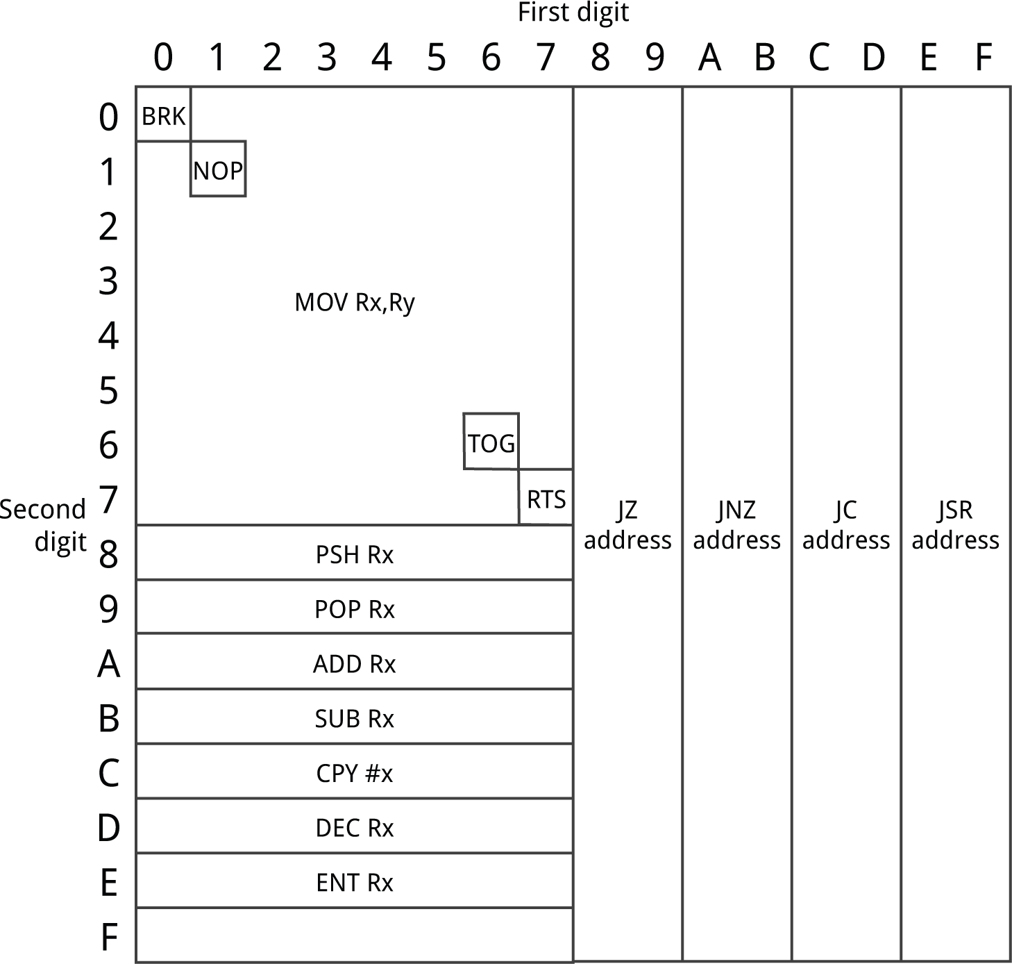
The following diagram shows how the 256 possible opcodes are assigned to the different instructions:
Using the Tiny Machine-Code Monitor
To turn on the Tiny Machine-Code Monitor press the ON button. The bottom line of the display will then show the address of the first memory location in hexadecimal, 00, and its contents in hexadecimal; initially this will also be 00. This is followed by a label, L00:, and the assembler code for the instruction, BRK:

Entering a program
You can edit the contents of the location shown on the bottom line of the display by pressing any of the alphanumeric keys 0 to 9 or A to F. For example, enter '66', the opcode for the TOG instruction which toggles the LED. The line will change to:

In the monitor you can use ▼ or ▲ to step forwards or backwards in memory, displaying the contents of successive locations. Press ▼ to step to the next location and enter '1D', the opcode for DEC R1.
Likewise, in location 02 enter 'A1', and in location 03 enter '80':

You've entered the MINIL version of the classic Blink program.
Running the program
To run the program press RUN. If you've entered the program correctly the LED should blink.
Press ON to interrupt the program and return to the monitor.
Displaying and entering values
You can display the contents of a register, and enter a new value into a register, using the ENT instruction. Try entering the following program:

When you press RUN the ENT R0 instruction displays the contents of register R0. Initially all the registers are set to zero:

Enter a new value, using the keys 0 to 9, and press RUN to continue. The program adds the number to itself, doubling it, and displays the result. Pressing RUN again repeatedly doubles the number. To exit press ON.
The circuit
The circuit uses an ATtiny85 to read the keypad, drive the OLED display, and interpret the MINIL program. It takes advantage of my One Input 20-key Keypad Interface which uses carefully chosen resistors to give a different voltage for each key at a single analogue input on the ATtiny85. In addition, the ON key is used to wake the processor up from sleep by defining PB3 as a digital input with a pin-change interrupt, taking advantage of the fact that this key is connected to GND with a pullup resistor.
The OLED display is connected via a two-wire I2C interface, and a fourth I/O line is used to provide an LED which you can control from a MINIL program:
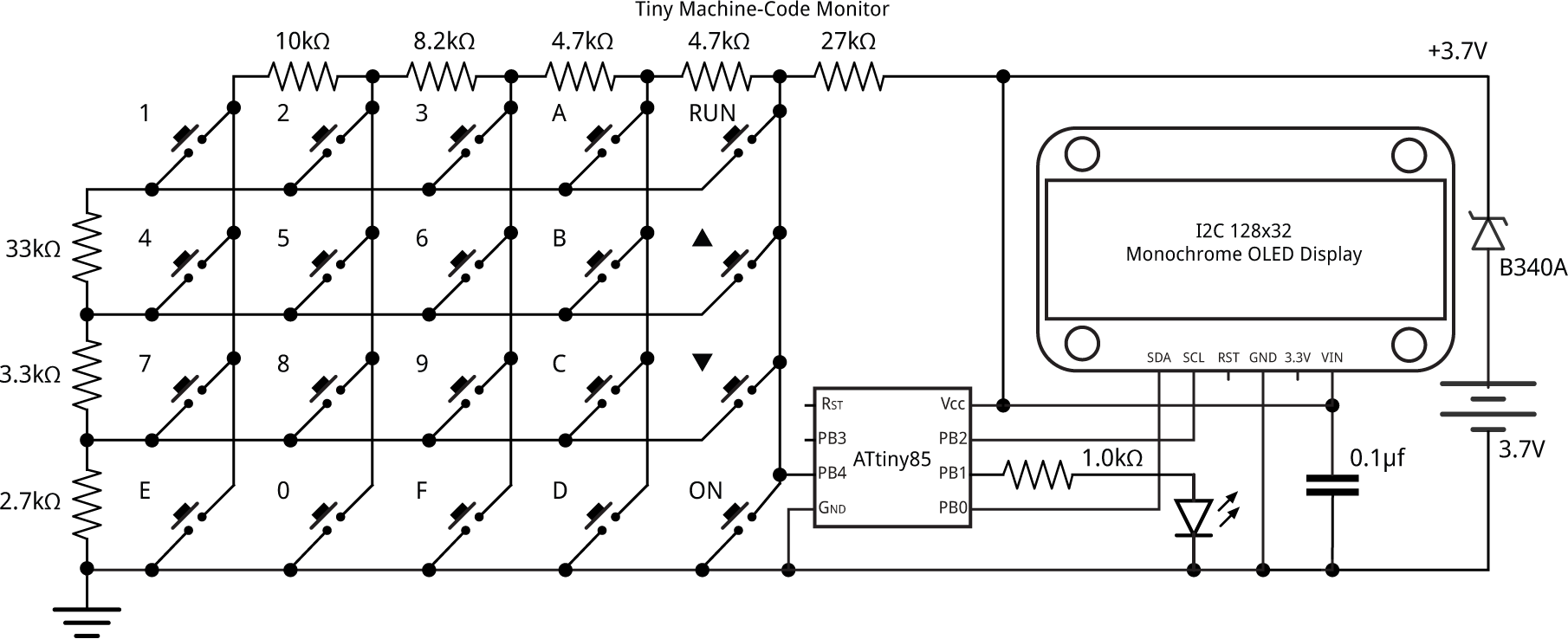
The circuit of the Tiny Machine-Code Monitor, based on an ATtiny85.
I included a Schottky diode in series with the battery to protect the circuit if the battery is inadvertently inserted the wrong way round.
► Parts list
Construction
I designed a board in Eagle and sent it to PCBWay for fabrication [7]. There's a link to the Eagle files at the end of the article if you want to make yourself a board.
The circuit board is designed around low-cost through-hole tactile buttons that you can get from suppliers for as little as 4 cents/pence each [8], or less from Banggood [9]. The display is an OLED 128x32 I2C display; I used a low-cost module from AliExpress [10] held in place with a double-sided self-adhesive foam pad. The board also accommodates Adafruit's version [11].
The circuit is powered by a 3.7V AAA-sized Lithium battery [12] which is retained by two clips [13] soldered to the PCB. If you prefer you could attach a battery holder for two 1.5V AAA cells and power it from that instead.
The ATtiny85 is in an SOIC package, and the resistors, capacitor, and LED are all 0805 size, so they should be relatively easy to solder by hand. To keep the board as compact as possible the SMD components apart from the LED are mounted on the reverse of the board:
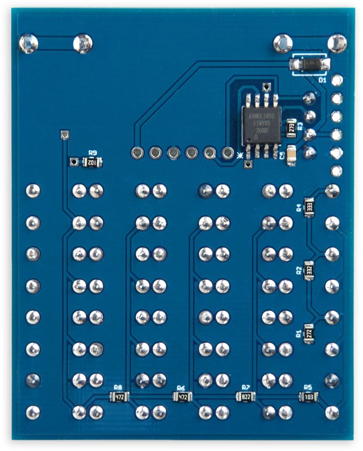
The back of the Tiny Machine-Code Monitor PCB showing the surface-mount components.
A 6-way connector at the edge of the board gives access to the signals needed for programming the ATtiny85.
The program
The program consists of four main sections to handle the keyboard, display, MINIL interpreter, and MINIL disassembler.
The keyboard interface is based on my earlier One Input 20-key Keypad Interface,
The display interface uses the same routines as my earlier Tiny Function Generator, which used the same I2C OLED display.
To avoid the need for an on/off switch the program blanks the display and puts the processor to sleep while waiting for key input if no key has been pressed for 30 seconds. To turn it back on press the ON key. The normal current consumption is around 12mA, but in sleep mode the current consumption drops to about 8µA, which is negligible. Note that the monitor doesn't go to sleep while a MINIL program is running, as some programs could have execution times greater than the timeout.
The MINIL interpreter
The MINIL interpreter is implemented by the routine Run():
void Run () {
  int pc = 0, sp = 0;
  boolean zero = false, carry = false;
  uint8_t byte, high, low, jump;
  err = false;
  for (int r=0; r<8; r++) reg[r]=0;
  do {
    byte = mem[pc++];
    high = byte>>4 & 0xf;
    low = byte & 0xf;
    jump = byte & 0x1f;
    if (high == 0 && low == 0) {
      error(PSTR("BREAK"));
    } else if (high == 6 && low == 6) {
      digitalWrite(1, !digitalRead(1));
    } else if (high == 7 && low == 7) {
      if (sp == 0) error(PSTR("STACK <"));
      pc = stk[--sp];
    } else if (high < 8 && low < 8) {
      reg[high] = reg[low];
    } else if (high < 8) {
      // Single register operations
      if (low == 0x8) {
        if (sp >= StackSize-1) error(PSTR("STACK >"));
        stk[sp++] = reg[high];
      } else if (low == 0x9) {
        if (sp == 0) error(PSTR("STACK <"));
        reg[high] = stk[--sp];
      } else if (low == 0xA) {
        carry = (reg[0] + reg[high]) > 9999;
        reg[0] = reg[0] + reg[high];
        if (carry) reg[0] = reg[0] - 10000;
        zero = reg[0] == 0;
      } else if (low == 0xB) {
        carry = reg[high] > reg[0];
        reg[0] = reg[0] - reg[high];
        if (carry) reg[0] = reg[0] + 10000;
        zero = reg[0] == 0;
      } else if (low == 0xC) {
        reg[0] = high;
      } else if (low == 0xD) {
        carry = reg[high] == 0;
        reg[high]--;
        if (carry) reg[high] = 9999;
        zero = reg[high] == 0;
      } else if (low == 0xE) {
        err = enter(high);
      }
    } else if (high >= 0x8) {
      // Jumps
      if (high <= 0x9) { if (zero) pc = jump;}
      else if (high <= 0xB) { if (!zero) pc = jump;}
      else if (high <= 0xD) { if (carry) pc = jump;}
      else {
        if (sp >= StackSize-1) error(PSTR("STACK >"));
        stk[sp++] = pc;
        pc = jump;
      }
    }
  } while (err == false && digitalRead(4) == 1);
  digitalWrite(1, LOW);
}
Errors call error() to display a message and return to the monitor. While a MINIL program is running you can press the ON key to interrupt execution and return to the monitor; this is useful if your program gets stuck in a loop.
The MINIL disassembler
The MINIL disassembler is handled by the routine Disassemble(). It has a similar structure to the MINIL interpreter, but instead of executing instructions it displays the assembler code as a line of text on the display:
void Disassemble (int pc) {
  uint8_t high, low, jump;
  Column = 0;
  //
  // Address and instruction
  Pbyte(pc); Pchar(' ');
  Pbyte(mem[pc]); Pchar(' ');
  //
  // Optional label
  if (Label(pc)) { Pchar('L'); Pbyte(pc); Pchar(':'); Pchar(' '); }
  else Print(PSTR("     "));
  //
  // Assembler code
  uint8_t byte = mem[pc];
  high = byte>>4 & 0xf;
  low = byte & 0xf;
  jump = byte & 0x1f;
  if (high == 0 && low == 0) {
    Print(PSTR("BRK      "));
  } else if (high == 1 && low == 1) {
    Print(PSTR("NOP      "));
  } else if (high == 6 && low == 6) {
    Print(PSTR("TOG      "));
  } else if (high == 7 && low == 7) {
    Print(PSTR("RTS      "));
  } else if (high < 8 && low < 8) {
    Print(PSTR("MOV R")); Phex(high); Print(PSTR(",R")); Phex(low);
  } else if (high < 8) {
    if (low == 0x8) Print(PSTR("PSH R"));
    else if (low == 0x9) Print(PSTR("POP R"));
    else if (low == 0xA) Print(PSTR("ADD R"));
    else if (low == 0xB) Print(PSTR("SUB R"));
    else if (low == 0xC) Print(PSTR("CPY #"));
    else if (low == 0xD) Print(PSTR("DEC R"));
    else if (low == 0xE) Print(PSTR("ENT R"));
    else if (low == 0xF) Print(PSTR("??? R"));
    Phex(high); Print(PSTR("   "));
  } else if (high >= 0x8) {
    if (high <= 0x9) Print(PSTR("JZ "));
    else if (high <= 0xB) Print(PSTR("JNZ"));
    else if (high <= 0xD) Print(PSTR("JC "));
    else Print(PSTR("JSR"));
    Print(PSTR(" ")); Pchar('L'); Pbyte(jump); Print(PSTR("  "));
  }
}
Each line is prefixed by the hexadecimal address and hexadecimal opcode. If the line is the destination for a jump instruction elsewhere in the program the disassembler inserts a label, such as L05:, where 05 is the hexadecimal address of the statement. This is followed by the opcode, and if appropriate, registers or label.
Compiling the program
I compiled the program using Spence Konde's ATTiny Core [14]. Choose the ATtiny25/45/85 option under the ATtinyCore heading on the Board menu. Then choose Timer 1 Clock: CPU, B.O.D. Disabled, ATtiny85, 8 MHz (internal) from the subsequent menus.
I used the Sparkfun Tiny AVR Programmer [15] connected to the 6-pin connecter to the left of the display. Choose Burn Bootloader to set the fuses appropriately, if necessary, and then choose Upload to upload the program.
Here's the whole Tiny Machine-Code Monitor program: Tiny Machine-Code Monitor Program.
Alternatively, get it on GitHub here together with the Eagle files for the PCB: Tiny Machine-Code Monitor on GitHub.
Or order a board from PCBWay here: Tiny Machine-Code Monitor Board.
Or order a board from OSH Park here: Tiny Machine-Code Monitor Board.
Programming challenges
I've given several example programs here: MINIL Programs.
If you'd like to try your hand at some other programming challenges, within the limitations of the MINIL instruction set, here are some suggestions:
- Find all the perfect numbers less than 10000 [16].
- For any n and r find nCr, the number of combinations of n thing taken r at a time.
- Find the nth Fibonacci number.
- Find the sum of the squares of the digits of a number; for example, 2018 should give 69.
Updates
11th August 2018: Corrected a mistake in the circuit diagram: the keyboard should connect to PB4 (not PB3). Thanks to Mike McLaren for bringing that to my attention.
16th August 2018: Added a parts list: Parts list.
Further suggestions
I'd be the first to admit that the MINIL instruction set is a bit limited. Fortunately, it's easy to extend it. You can either add new operations using the unimplemented instructions, or replace some of the instructions with your own.
It should also be fairly simple to add a debugger to the Tiny Machine-Code Monitor, including features such as breakpoints, and single stepping, with a display showing the contents of the program counter, stack pointer, and registers at each step.
Another extension would be the ability to save programs in EEPROM, so you can load them again without having to key them in. With the current maximum program size of 64 bytes the ATtiny85 EEPROM would have room for eight programs.
- ^ Also known as the Little Man Computer; see Little man computer on Wikipedia.
- ^ MEK6800D2 on Wikipedia.
- ^ KIM-1 on Wikipedia.
- ^ MK14 on Wikipedia.
- ^ Acorn System 1 on Wikipedia.
- ^ MINIL Interpreter in "Mk14 Further Application Programs" by David Johnson-Davies, pp. 18-23, published by Science of Cambridge Ltd, Cambridge, UK.
- ^ PCBWay PCB prototyping service.
- ^ FSM4JH - Tactile Switch, Non Illuminated on Farnell.com.
- ^ Geekcreit 100pcs Mini Micro Tactile Touch Switch on Banggood.
- ^ 0.91 inch 128x32 I2C IIC Serial OLED LCD Display Module on AliExpress.
- ^ Monochrome 128x32 I2C OLED graphic display on Adafruit.
- ^ Lixada 4PCS AAA 10440 600mAh 3.7V Rechargeable Lithium Battery on Amazon.
- ^ 82 Keystone Battery Clip AAA on Farnell.
- ^ ATTinyCore on GitHub.
- ^ Tiny AVR Programmer on Sparkfun.
- ^ A perfect number is a number that is equal to the sum of its divisors, excluding the number itself. For example, 6 is perfect because 6 = 1 + 2 + 3.
blog comments powered by Disqus
