Pocket Op Amp Lab Cookbook
26th January 2021
This cookbook gives examples of using my Pocket Op Amp Lab to experiment with some practical applications of the configurable op amps in Microchip's new DB-series microcontrollers.
Voltage follower
Perhaps the simplest configuration of an op amp is the voltage follower. The output is connected back to the negative input, and the signal is connected to the positive input.
On the AVR128DB28 you can configure two voltage followers by setting the menu options as follows:
This mode provides a good way to test that the op amps in your circuit are working correctly. With them connected like this the output should follow the voltage on the input pin. Connecting it to GND will set the output to zero, and connecting it to VCC will set the output to the supply voltage.
Although the voltage follower only provides a gain of 1, it provides a high input impedance and low output impedance, and so is often used as a buffer.
DAC output buffer
One application of the voltage follower is to buffer the output from the DAC, which on its own has limited drive capability.
First set up the DAC as a waveform generator to produce a low-frequency triangle wave by adding these statements to the end of setup():
  VREF.DAC0REF = VREF_REFSEL_VDD_gc;                // VDD reference
  DAC0.CTRLA = DAC_OUTEN_bm | DAC_ENABLE_bm;        // Enable DAC
Then put the following code in loop() to generate a triangle wave of about 167Hz:
uint16_t DacValue = 0;

void loop () {
  uint16_t Mask = (int)(DacValue<<5)>>10;
  DAC0.DATA = DacValue<<6 ^ Mask;
  DacValue++;
}
The triangle wave will be available at the DAC output, PD6:
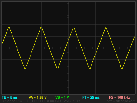
Then set up the Pocket Op Amp Lab as follows to use op amp 0 to buffer the DAC output (op amp 1 is not used):
The triangle wave will be available at the output OUT0, on PD2. With the buffered output you can drive an 8Ω loudspeaker via a 220µF electrolytic capacitor:
Constant current source
The op amps in the AVR128DB28 can be used as a simple adjustable constant current source [1], to drive a device that requires a constant current, such as an LED.
Set up op amp 0 in the Pocket Op Amp Lab as follows:
Connect up an external 330Ω resistor and LED as follows:
The op amp keeps the voltage across the LED at a fixed value determined by the resistor divider. With a supply voltage of 5V, and the resistor divider set as shown above, this will keep the voltage at INN0 to 1/16 x 5 or 0.3125V, giving a current through the resistor and LED of 0.95mA.
You can adjust the current by changing the MUXWIP setting:
| MUXWIP | R1 | R2 | Current |
| WIP7 | 1R | 15R | 0.95mA |
| WIP6 | 2R | 14R | 1.9mA |
| WIP5 | 4R | 12R | 3.8mA |
| WIP4 | 6R | 10R | 5.7mA |
| WIP5 | 8R | 8R | 7.6mA |
| WIP3 | 12R | 4R | 11.4mA |
| WIP2 | 14R | 2R | 13.3mA |
| WIP1 | 15R | 1R | 14.2mA |
Note that in practice the maximum current you can set will be limited by the voltage drop of the LED.
Electret microphone interface
A good application of the DB-series op amp peripheral is to amplify the input from an electret microphone to levels that can then be used to drive an ADC. The following application uses a low-cost electret microphone to flash an LED to indicate the presence of a sound, and is based on a Microchip application note [2]. I used an electret microphone from Adafruit with -44dB sensitivity and a 20Hz-20kHz frequency response [3].
Set up the Pocket Op Amp Lab as follows:
The total gain is (15/1) x (14/2) or 105. The output at PD5 will be centred about VDD/2.
To give a visual indication of the op amp output connect it to an LED as follows:
The LED will flash in response to sounds from the microphone.
You can also read the 10-bit analogue value at OUT1 on PD5 (Arduino pin 17) with analogRead():
int val = analogRead(17) - 512;
This sets val to a value between -512 and 511, where 0 corresponds to no output from the microphone.
Oscillator
A single op amp can be configured as an oscillator by adding a few external components. First configure op amp 0 in the Pocket Op Amp Lab as follows:
Then connect up the external components as follows:
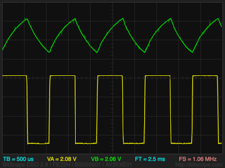
The bottom of the internal resistor divider is connected to the INP0 pin (PD1), which is held at VDD/2 by the two external 10kΩ resistors. The capacitor is alternately charged and discharged between 3/4VDD and 1/4VDD, switching the output of the op amp between GND and VDD. The 47kΩ resistor and 10nF capacitor determine the time constant, which is given by f = 1/(2.2RC). With these values the frequency is about 967Hz.
I've estimated the value of R in the resistor dividers to be about 4kΩ, so 8R is equivalent to 32kΩ, and the equivalent circuit for the oscillator is as follows:
The following trace shows the triangle wave at the negative input, INN0, and the square wave at the Output, OUT0:
- ^ AN3632 Constant-Current Driver Using the Analog Signal Conditioning (OPAMP) Peripheral on Microchip.com.
- ^ AN3631 Low-BOM Microphone Interface Using the Analog Signal Conditioning (OPAMP) Peripheral on Microchip.com.
- ^ Electret Microphone 20Hz-20KHz Omnidirectional on Adafruit.com.
blog comments powered by Disqus